Shield tunneling machine cutterhead driving system based on hydro-viscous drive

A cutter head drive and liquid viscosity technology, which is applied in mining equipment, earthwork drilling, tunnels, etc., can solve the problems of high excavation cost, easy damage to the motor, and low driving power, so as to improve the starting reliability, Protect safe operation and reduce the effect of starting current

Inactive Publication Date: 2014-08-06
ZHEJIANG UNIV
View PDF5 Cites 5 Cited by
  • Summary
  • Abstract
  • Description
  • Claims
  • Application Information

AI Technical Summary

Problems solved by technology

However, the existing motor-driven shield machines use ordinary wet clutches to control the power transmission of the motors, and ordinary wet clutches can only work in the on-off state, resulting in large impacts when loading, and complex geological conditions—such as hard rock formations In the composite stratum intersecting with the soft soil layer, the cutterhead is subjected to huge cutting torque changes, which can easily cause the cutterhead to be stuck, which in turn will cause the motor to be stuck and damage the motor and the main bearing.
In the actual excavation project, due to the frequent burnout of the cutter head motor of the shiel

Method used


Image

  • Shield tunneling machine cutterhead driving system based on hydro-viscous drive
  • Shield tunneling machine cutterhead driving system based on hydro-viscous drive
  • Shield tunneling machine cutterhead driving system based on hydro-viscous drive

Examples


Embodiment

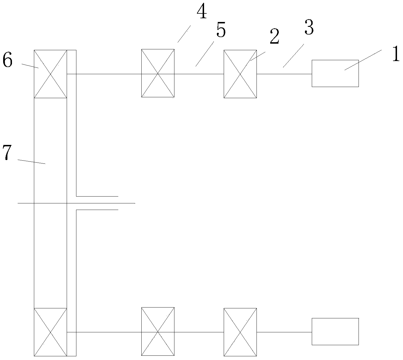
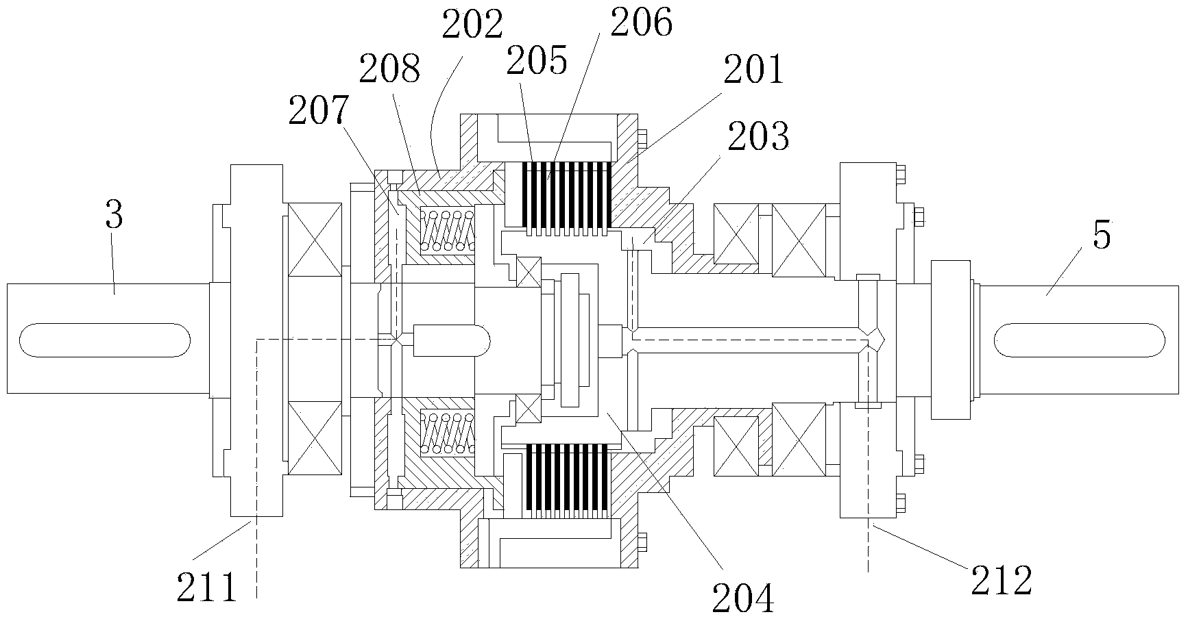
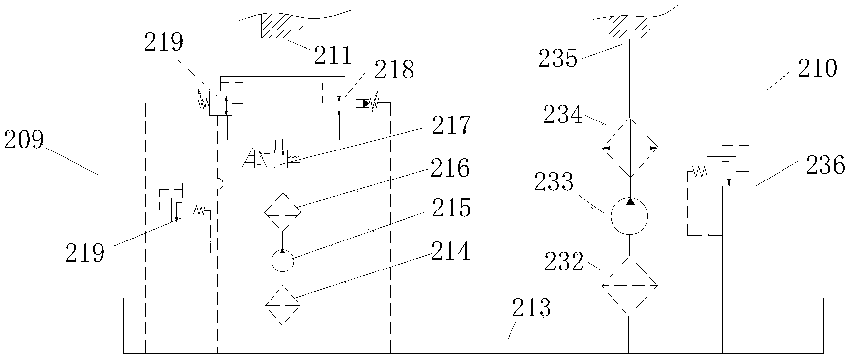
[0037] Embodiment: Shield machine cutter head drive system based on liquid viscous transmission, such as figure 1 with figure 2 As shown, it includes multiple groups of driving mechanisms, and the power source of each group of driving mechanisms is a variable frequency motor 1. The variable frequency motor 1 is connected to the transmission mechanism 2 through the input shaft 3 through the coupling, and the transmission mechanism 2 is connected to the mechanical mechanism through the output shaft 5 through the coupling. Reducer 4, the output shaft of the mechanical reducer 4 is connected to the cutter head drive pinion 6. The cutterhead drive pinion 6 of each group of drive mechanisms is meshed with the cutterhead drive gear 7 for driving the cutterhead, and the cutterhead drive pinion 6 transmits power to the cutterhead drive gear 7 for rotation, and the cutterhead drives the large gear 7 Then drive the cutter head on it to rotate. The transmission mechanism 2 includes an...


PUM


Abstract

The invention discloses a shield tunneling machine cutterhead driving system based on hydro-viscous drive. The shield tunneling machine cutterhead driving system comprises multiple groups of driving mechanisms. Each group of driving mechanism is connected with a transmitting mechanism through an input shaft, the transmitting mechanism is connected with a cutterhead driving small gear with planetary deceleration through an output shaft, and the cutterhead driving small gear is in meshed transmission with a cutterhead driving large gear to drive a cutterhead to rotate. The shield tunneling machine cutterhead driving system is characterized in that a hydro-viscous drive mechanism comprises a driving drum fixed to the input shaft and a driven drum fixed to the output shaft. The driving drum is connected with multiple groups of main friction plates through splines, the driven drum is connected with multiple groups of auxiliary friction plates through splines, and the main friction plates and the auxiliary friction plates are arranged in a cross mode. A piston cavity is formed in the driving drum, a piston is arranged in the piston cavity, and the piston can drive the main friction plates to adjust the gaps between the main friction plates and the auxiliary friction plates. The shield tunneling machine cutterhead driving system based on the hydro-viscous drive has the advantages of being stepless in speed regulation, large in driving power, excellent in impact resistance and good in overload protection performance.

Description

technical field [0001] The invention relates to a shield machine cutterhead drive system, in particular to a shield machine cutterhead drive system driven by a motor and based on liquid viscous transmission. Background technique [0002] Since ancient humans dug caves as the earliest habitats, humans have been developing their living space underground. With the development of society, the scale of cities continues to expand, the population expands rapidly, and human demand for space continues to grow. The limited space on the surface of the earth prompts humans not only to explore outer space, but also to direct the attention of space expansion to the inner space of the earth. Underground space has been placed in front of us as a resource at our fingertips. The use of underground space development for road traffic and transportation construction has become a construction hotspot in the transportation industry. During the long-term development of human society, human tunnel...

Claims


Application Information

Patent Timeline
IPC IPC(8): E21D9/08E21D9/093
Inventor 魏建华邵威方锦辉
Owner ZHEJIANG UNIV
Why Eureka
Try Eureka