Shell-and-tube heat exchanger and method for machining plate holes in shell-and-tube heat exchanger

A technology of shell-and-tube heat exchangers and plate holes, which is applied in the field of heat transfer, can solve problems such as unfavorable shell-side fluid uniform flow, achieve accurate prediction of heat transfer performance and stress distribution, promote uniform flow, and reduce modeling difficulty Effect

Active Publication Date: 2014-08-06
NANJING UNIV OF TECH
View PDF6 Cites 5 Cited by
  • Summary
  • Abstract
  • Description
  • Claims
  • Application Information

AI Technical Summary

Problems solved by technology

[0011] The present invention aims at the disadvantage that the spatial distribution of heat exchange tubes in the existing shell-and-tube heat exchanger is not conducive to the uniform flow of shell-side fluid. The heat exchange tubes are arranged layer by layer, and the heat exchange tubes are evenly distributed in the circumferential direction, and the annular and disc-shaped baffles arranged at intervals are used to realize the uniform flow of the shell side fluid

Method used


Image

  • Shell-and-tube heat exchanger and method for machining plate holes in shell-and-tube heat exchanger
  • Shell-and-tube heat exchanger and method for machining plate holes in shell-and-tube heat exchanger
  • Shell-and-tube heat exchanger and method for machining plate holes in shell-and-tube heat exchanger

Examples


Embodiment 1

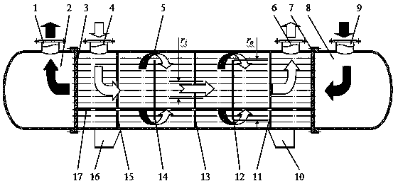
[0051] Design a heat exchanger, which is mainly composed of shell, tube sheet, heat exchange tube, tube box, baffle plate, etc. The material is not limited, such as figure 1 shown. The tube-side fluid enters from the tube-side inlet nozzle 9 on the right tube box 8, flows through the heat exchange tube bundle 17 from left to right, collects in the left tube box 2, and is discharged from the tube-side outlet nozzle 1; the shell-side fluid flows from the cylindrical The shell side inlet joint 4 of the cylinder 5 enters, and under the action of the baffle, the shell side flows radially, forming a cross flow with the tube side fluid, and finally discharges through the shell side inlet joint 7 of the cylinder 5 .

[0052] The heat exchange tube bundle is fixed by the left tube plate 3 and the right tube plate 7 welded to the cylinder body 5, and passes through each baffle. Both the tube sheet and the baffle (ring-shaped and disc-shaped) have plate holes consistent with the outer d...

Embodiment 2

[0058] According to the plate hole arrangement principle of the present invention, the following steps are adopted to determine the position of the plate holes.

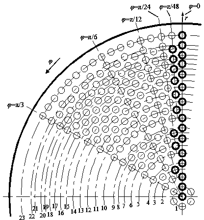
[0059] ①As attached figure 2 As shown, a polar coordinate system is established, the origin of the coordinate system is placed at the center of the tube sheet, the radial coordinate is r, and the circumferential coordinate is . Set the first plate hole in the center of the tube plate.

[0060] ② Determine the minimum spacing d of the plate holes s . With (r=0) as the center, d s Make the first concentric circle for the radius, and set 6 plate holes evenly on the concentric circle according to the principle (3), and the center of one of the plate holes is located at superior. The spacing of these 6 plate holes satisfies d s ≥1.25d requirement.

[0061] ③According to the method for determining the radius of concentric circles, the radius of the second concentric circle is calculated to be 2d s , 6 plate hol...


PUM


Abstract

The invention relates to a heat transfer technology and provides a shell-and-tube heat exchanger and a method for machining plate holes in the shell-and-tube heat exchanger. According to the technology, heat exchange tubes are distributed in a radial topological mode in cooperation with circular-ring-shaped and disk-shaped baffle plates which are arranged alternately, so that shell-pass fluid uniformly flows through all the heat exchange tubes in the radial direction, and the utilization rate of the heat exchange tubes is increased. The shell-and-tube heat exchanger mainly comprises a barrel body, tube plates, tube boxes, the heat exchange tubes and the baffle plates. The baffle plates comprise the circular-ring-shaped baffle plates and the disk-shaped baffle plates, the circular-ring-shaped baffle plates and the disk-shaped baffle plates are arranged alternately, and the total number of the baffle plates is an odd number. The heat exchange tubes are arranged on concentric circles with different diameters with the symmetrical axis of the heat exchanger as the center and are distributed evenly in the circumferential direction. The spacing between the heat exchange tubes is not a definite value, and the minimum spacing is 1.25 times larger than or equal to the outer diameter of each heat exchange tube.

Description

Technical field: [0001] The invention relates to a heat transfer technology, in particular to a shell-and-tube heat exchanger. Based on the fractal theory, the radial topology is used to arrange the heat exchange tubes, and the alternately arranged disc-shaped and annular baffles maximize the uniformity of the shell-side fluid flow to improve the utilization of the heat exchange tubes . Background technique: [0002] Heat exchange equipment can be divided into: condenser, evaporator, reheater, superheater, etc. according to the function, and can be divided into: shell and tube heat exchanger, finned tube heat exchanger, plate heat exchanger according to the characteristics of heat exchange components Heater (including plate-fin heat exchanger and plate-fin heat exchanger). [0003] The shell and tube heat exchanger is the most widely used heat exchanger in the process industry. It is mainly composed of shell, tube sheet, heat exchange tube, head, baffle and other componen...

Claims


Application Information

Patent Timeline
Patent Type & Authority Applications(China)
IPC IPC(8): F28D7/16F28F9/02F28F9/24
Inventor 周剑锋吴士伟陈瑶邵春雷顾伯勤
Owner NANJING UNIV OF TECH
Why Eureka
Try Eureka