A thermal protection system optimization design method and system based on an agent model

A technology of system optimization and design method, applied in computer-aided design, design optimization/simulation, calculation, etc., can solve the problems of human error, many design variables of thermal protection structure, and large margin of design results.

Pending Publication Date: 2019-04-09
CHINA ACAD OF LAUNCH VEHICLE TECH
View PDF8 Cites 2 Cited by
  • Summary
  • Abstract
  • Description
  • Claims
  • Application Information

AI Technical Summary

Problems solved by technology

However, there are many variables in the design of thermal protection structures, including many typical structural dimensions, material performance parameters, etc., and the constraints are complex, including heat protection, heat insulation, strength, modal, etc.
In the traditional thermal protection system design method, there is no way to consider many factors, the design result margin is too large, the design result is too conservative, and it is difficult to directly achieve the optimal design
Moreover, the design efficiency of traditional methods is low, and in some cases, human error is prone to occur, resulting in design risks

Method used


Image

  • A thermal protection system optimization design method and system based on an agent model
  • A thermal protection system optimization design method and system based on an agent model
  • A thermal protection system optimization design method and system based on an agent model

Examples


Embodiment Construction

[0104] The present invention will be further described in detail below in conjunction with the drawings and specific embodiments:

[0105] The flight thermal protection system is located on the outermost side of the aircraft, and its internal structure is protected against heat insulation. Generally, it is formed by splicing a plurality of thermal protection structural parts, and its overall dimensions are consistent with those of the aircraft.

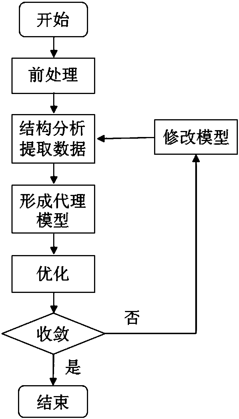
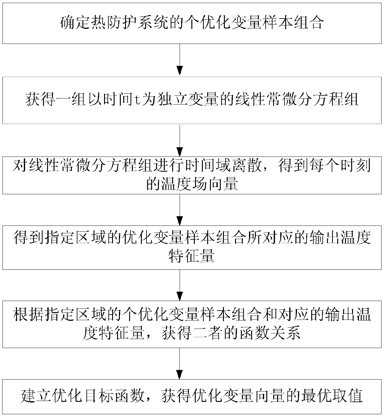
[0106] Such as figure 1 Shown is the schematic diagram of the thermal protection system optimization design method based on the agent model of the present invention; figure 2 Shown is the flow chart of the thermal protection system optimization design method based on the proxy model of the present invention; the flow chart of the thermal protection system optimization design method based on the proxy model of the present invention specifically includes the following steps:

[0107] Step (1): Determine the design parameters of each thermal ...


PUM


Abstract

The invention relates to a thermal protection system optimization design method and module based on an agent model, and the method comprises the steps: carrying out the finite element analysis on thebasis of a small sample, carrying out the fitting of a response surface model, carrying out the large optimization analysis on the response surface model, greatly reducing the calculation amount, andimproving the efficiency. Meanwhile, a linear constant differential equation set of the thermal protection analysis model is solved by adopting a time integration method, so that the resolving time issaved; According to the invention, geometric dimensions are also considered; A thermal analysis model is established under the influence of a plurality of optimization variables of the density, the specific heat capacity, the heat conductivity and the surface radiance of the thermal protection system on thermal protection, so that the thermal protection system optimization design has higher precision, and a more scientific and accurate basis is provided for the thermal protection system design of the hypersonic flight vehicle; In addition, the method effectively reduces the design allowance of the thermal protection system, reduces the weight of the thermal protection system and reduces the power consumption of the aircraft.

Description

Technical field [0001] The invention relates to an optimized design method and a design module of a thermal protection system based on an agent model, and belongs to the related field of hypersonic thermal protection design. Background technique [0002] Thermal Protection System (TPS) is one of the most important systems of hypersonic aircraft. It protects the structural integrity of the system and the temperature conditions inside the aircraft under the high temperature and harsh environment of aerodynamic heating of the aircraft. The reliability and structural integrity of the thermal protection system are very important to the safety of aerospace vehicles. The accidents caused by its failure account for a considerable proportion of the mission failures of the aerospace / aerospace vehicles. Therefore, thermal protection technology is the most important in the design of super aircraft. The key link. [0003] In the design process of the thermal protection system, the most critica...

Claims


Application Information

Patent Timeline
IPC IPC(8): G06F17/50G06F17/13G06F17/15G06F17/16
CPCG06F17/13G06F17/15G06F17/16G06F2119/08G06F30/23G06F30/15Y02T90/00
Inventor 辛健强洪文虎陈景茂董永朋徐腾飞尹琰鑫屈强任冲王静姚星合王润
Owner CHINA ACAD OF LAUNCH VEHICLE TECH
Why Eureka
Try Eureka