Vertical firework tube shaper
A firework tube and vertical technology, applied in pyrotechnics, offensive equipment, weapon types, etc., can solve problems such as poor equipment operation, reduced production efficiency, vertical paper tube jamming, etc., to avoid adjustment intervention work, dust and The effect of low noise pollution and preventing jamming and confusion
- Summary
- Abstract
- Description
- Claims
- Application Information
AI Technical Summary
Problems solved by technology
Method used
Image
Examples
Embodiment 1
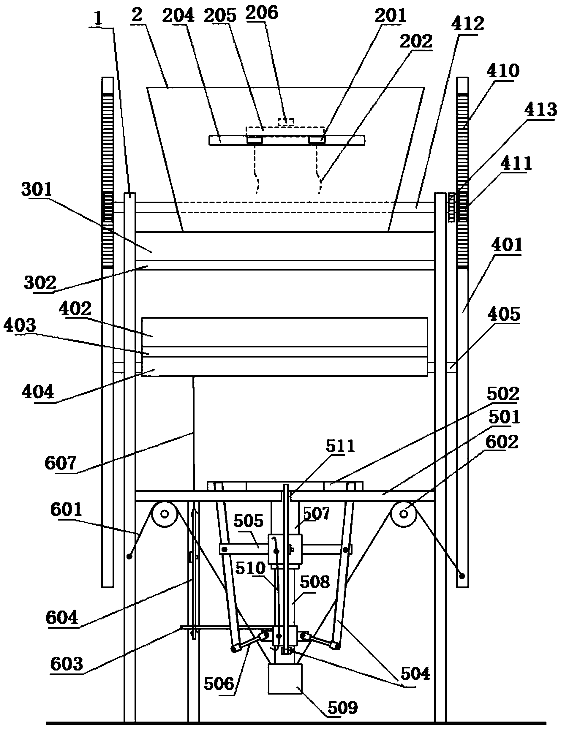
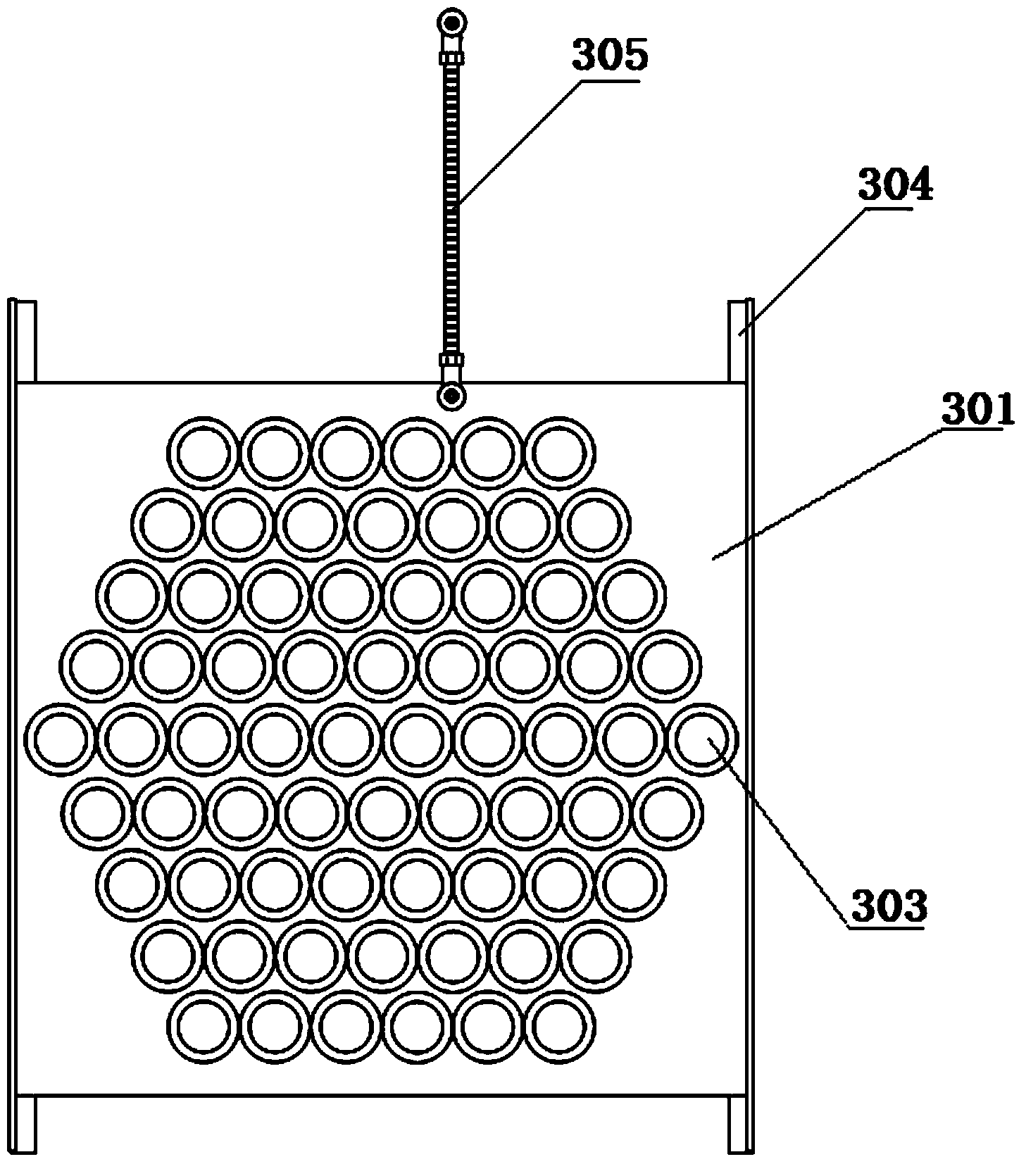
[0041] Embodiment 1: Referring to the accompanying drawings, reflecting a specific structure of the present invention, the vertical cake forming machine for fireworks tubes includes a hopper 2 loaded with fireworks tubes at the upper end of the frame 1, and a flexible carding mechanism is provided in the hopper 2, so that The bottom of the hopper 2 is provided with a material guiding mechanism, a feeding mechanism and a forming mechanism in sequence from top to bottom:
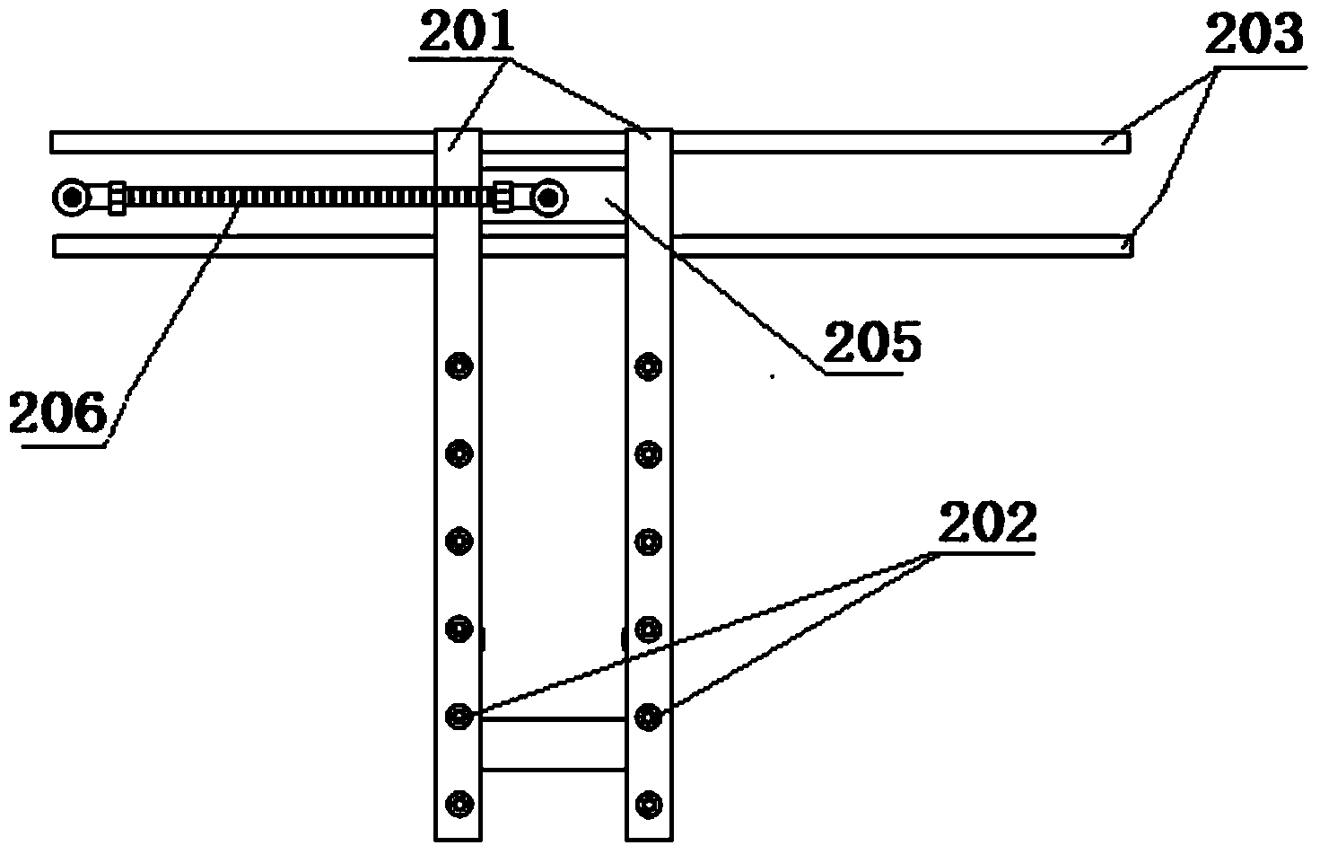
[0042] see figure 1 , 2 , 12. The flexible combing mechanism includes two crossbeams 201 connected to the first driving transmission mechanism to reciprocate linearly along the guide rail 203, and a number of flexible combing strips 202 arranged in a comb-like arrangement are distributed on the crossbeam 201; one end of the crossbeam 201 is fixedly connected to the guide rail 203 The slide block, the other end is sleeved in the installation groove 204 that hopper 2 sidewalls offer. The composition of the fir...
Embodiment 2
[0051] Example 2: see Figure 15 , the difference from Embodiment 1 is that the flexible carding structure also includes two movable hopper baffles 707 placed on the left and right sides of the hopper, the movable hopper baffles 707 are affixed to the slide block of the guide rail 703, and the movable hopper The baffle 707 is connected to the beam 701 through a wire rope 708 . When the crossbeam 701 reciprocates left and right, the steel wire rope 708 drives the two movable hopper baffles 707 to swing along the guide rail 703, so that the fireworks tubes in the hopper are concentrated toward the middle of the hopper so as to fall into the material guide holes, avoiding the failure of the fireworks tubes in the dead corners to fall. phenomenon appears.
Embodiment 3
[0052] Embodiment 3: see Figure 16 , 17 , the difference from Embodiment 1 is that the locking mechanism structure adopts elastic pins, including a pin 805 and a compression spring 806 installed at the lower end of the side wall of the guide sleeve 802, and the tail of the pin 805 passes through a drag cable 808 and a tension spring. 810 is connected to the feeding mechanism; a pin chute 801 is provided at a corresponding position on the side wall of the guide shaft 803 , and a pin locking hole 809 is provided at the lower end of the pin chute 801 . When the guide shaft 803 and the counterweight 804 rise to the highest point, the pin 805 falls into the pin locking hole 809 under the action of the compression spring 806 , thereby locking the position of the guide shaft 803 . When the feeding mechanism puts down the fireworks tube and rises, the drag spring 810 pulled by the cable 808 overcomes the active force of the stage clip 806, and the pin 805 is pulled out, and the guid...
PUM
 Abstract
Description
Claims
Application Information
 - R&D
- Intellectual Property
- Life Sciences
- Materials
- Tech Scout
- Unparalleled Data Quality
- Higher Quality Content
- 60% Fewer Hallucinations
Browse by: Latest US Patents, China's latest patents, Technical Efficacy Thesaurus, Application Domain, Technology Topic, Popular Technical Reports.
© 2025 PatSnap. All rights reserved.Legal|Privacy policy|Modern Slavery Act Transparency Statement|Sitemap|About US| Contact US: help@patsnap.com


