
Ultra-sensitive spectral imaging astronomical telescope based on second-order compressed sensing and method

An astronomical telescope, compressed sensing technology, applied in telescopes, optics, spectrum surveys, etc., can solve the problem of unable to solve the problem of detection dimensions, the decline of imaging resolution, and the inability to obtain astronomical images and astronomical spectral information at the same time.

Inactive Publication Date: 2014-08-06
NAT SPACE SCI CENT CAS
View PDF2 Cites 17 Cited by
  • Summary
  • Abstract
  • Description
  • Claims
  • Application Information

AI Technical Summary

Problems solved by technology

[0005] However, it is very difficult for astronomical telescopes to obtain astronomical images and astronomical spectrum information at the same time. The most important difficulty is the problem of dimensionality.
Two-dimensional astronomical images and one-dimensional spectral information share three-dimensional information. According to the traditional information acquisition method, detectors with three dimensions are required, but this is obviously impossible at present. Therefore, a large number of existing astronomical telescopes only Can obtain astronomical image information or astronomical spectral information separately, but cannot obtain both information at the same time
At present, our country only has single-point APD detectors, and due to the limitation of the manufacturing process, there is no ability to produce array APDs; the maximum pixel of array APDs available internationally is only 128×128, which is far from reaching the requirements for obtaining high-resolution astronomical images. need
In addition, PMT does not have an array detector due to its working mechanism
One way to solve the problem of insufficient pixels of high-sensitivity detectors is to use point detectors to scan to achieve imaging. The problem brought about by this is that scanning detectors will consume a lot of time, greatly reducing the speed of image acquisition, and at the same time, different positions of the image The difference in the detection time of information, and the image shift during scanning will cause the decrease of imaging resolution
Another way is to assemble a large number of point detectors into an array for detection, but to obtain sufficient resolution, an extremely large number of single point detectors is required, and about 800,000 points are required to obtain an image of 1024×768 pixels Detector, resulting in extremely high cost, and there will be a serious duty cycle problem when splicing point detectors, resulting in a decrease in light collection effect, which in turn affects the sensitivity of the telescope
Therefore, none of these high-sensitivity detectors using the existing technology can solve the problem of the detection dimension of the spectral imaging astronomical telescope, and cannot simultaneously acquire astronomical images and astronomical spectral information
[0009] To sum up, the existing spectral imaging astronomical telescopes have the problems of too large image and spectral detection information dimensions and insufficient detector dimensions, and cannot achieve high-sensitivity detection
Due to the limitations of the working principle, the traditional spectral imaging astronomical telescopes are restricted in the way of realizing multi-dimensional detection and improving the detection sensitivity. The development of astrophysics urgently needs spectral imaging astronomical telescopes with higher sensitivity.

Method used

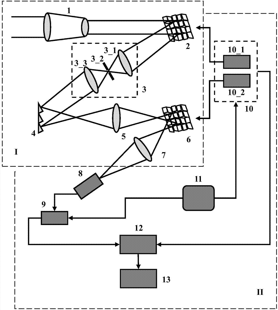
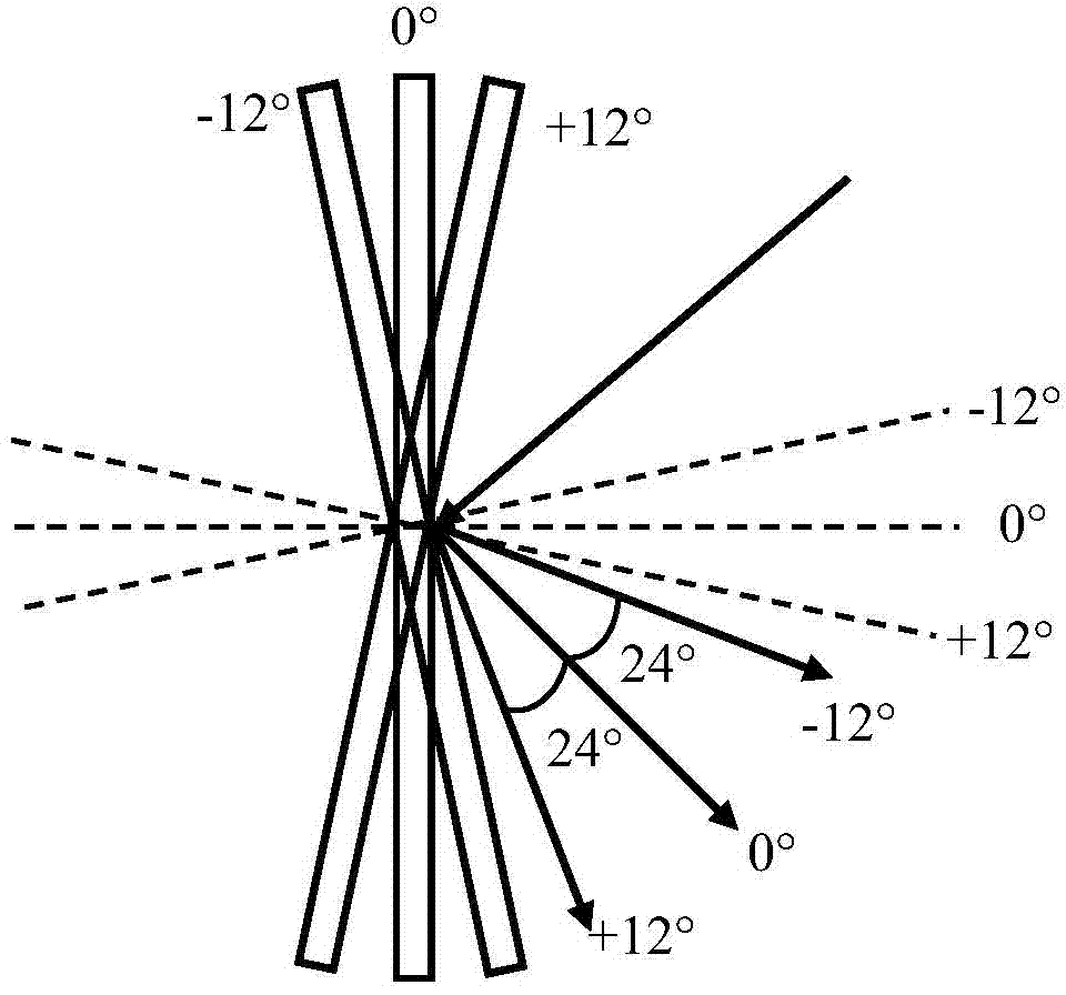
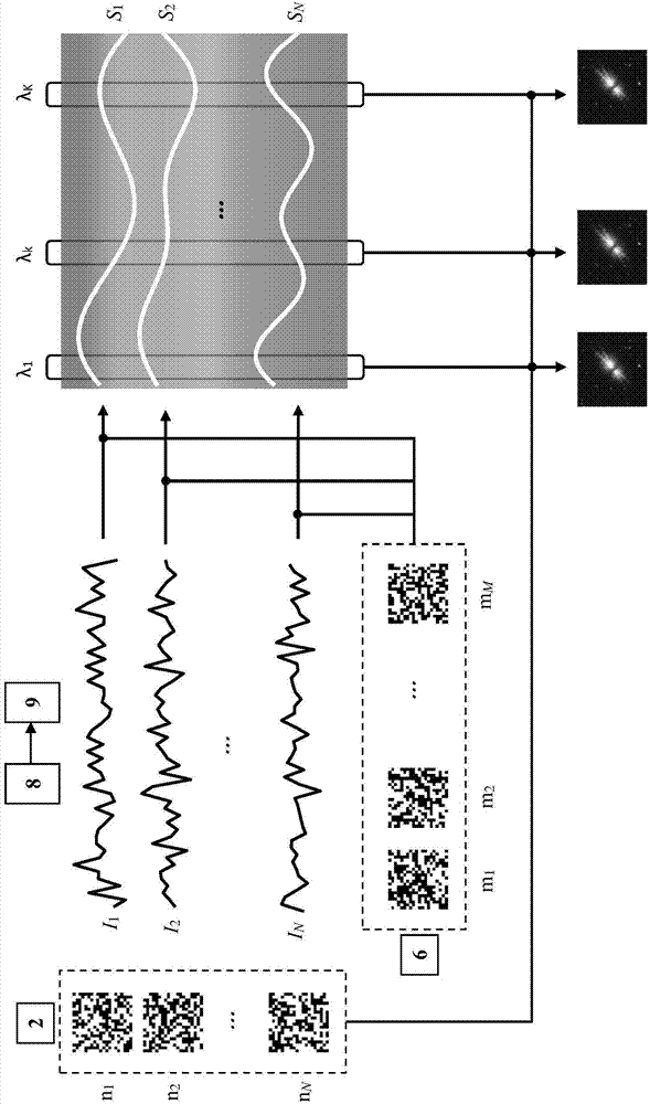

Image

  • Ultra-sensitive spectral imaging astronomical telescope based on second-order compressed sensing and method
  • Ultra-sensitive spectral imaging astronomical telescope based on second-order compressed sensing and method
  • Ultra-sensitive spectral imaging astronomical telescope based on second-order compressed sensing and method

Examples


Embodiment Construction

[0066] The present invention will be further described now in conjunction with accompanying drawing.

[0067] The ultra-sensitive spectral imaging astronomical telescope based on second-order compressed sensing of the present invention utilizes the principle of compressed sensing (Compressive Sensing, referred to as CS), which is a brand-new mathematical theory proposed by Donoho, Tao and Candès et al. According to compressed sensing, by randomly sampling the signal, the signal information can be sampled with a sampling number far lower than that required by the Nyquist / Shannon sampling theorem, and the original signal can be perfectly restored through a mathematical algorithm, and it has many advantages. High robustness. Compressed sensing is mainly divided into three steps: compressed sampling, sparse transformation and algorithm reconstruction; among them, compressed sampling refers to the process of sampling a signal with a measurement number less than the number of signal...


PUM


Abstract

The invention relates to an ultra-sensitive spectral imaging astronomical telescope based on second-order compressed sensing, which comprises an optical unit and an electric unit, wherein the optical unit comprises an astronomical telescope lens, a first spatial light modulator, a collimation part, a spectrometric part, a spectral convergence part, a second spatial light modulator and a collection part; the electric unit comprises a single-photon point detector, a counter, a random number generator, a control module, a data packet memory and a compressed sensing module; a celestial image is collected through the astronomical telescope lens, and is imaged to the first spatial light modulator; a randomly modulated light beam is collimated into parallel light, and the parallel light forms a spectral band through the spectrometric part; the spectral band is secondarily randomly modulated through the second spatial light modulator, and is finally collected in the single-photon point detector; and a compressed sensing algorithm is used for obtaining an astronomical target spectral image according to a photon count value and two groups of random matrixes.

Description

technical field [0001] The invention relates to the fields of optics and astronomy, in particular to an ultra-sensitive spectral imaging astronomical telescope and method based on second-order compressed sensing. Background technique [0002] Astronomical telescopes are an important tool for observing celestial bodies. It is no exaggeration to say that without the birth and development of telescopes, there would be no modern astronomy. With the improvement and improvement of the performance of telescopes in all aspects, astronomy is also undergoing a huge leap, rapidly advancing human understanding of the universe. [0003] According to different working bands, astronomical telescopes can be divided into optical telescopes and radio telescopes. Among them, optical telescopes mainly use visible light as the working band, and can be divided into ground astronomical telescopes and space astronomical telescopes according to different places of use. Due to the different optical...

Claims


Application Information

Patent Timeline
IPC IPC(8): G01J3/28G02B23/00
Inventor 刘雪峰翟光杰王超俞文凯姚旭日
Owner NAT SPACE SCI CENT CAS
Learn More