Bipolar-electrode electrochemiluminescence imaging electrolytic cell

A bipolar electrode, luminescence imaging technology, applied in chemiluminescence/bioluminescence, electrochemical variables of materials, analysis by chemical reaction of materials, etc. The problem of low reuse rate of pool channels, etc., achieves the effect of extending the scope of application, simple structure and reasonable design.

Inactive Publication Date: 2014-08-06
SHAANXI NORMAL UNIV
View PDF7 Cites 8 Cited by
  • Summary
  • Abstract
  • Description
  • Claims
  • Application Information

AI Technical Summary

Problems solved by technology

This method is complicated to manufacture, and because the bipolar electrode

Method used


Image

  • Bipolar-electrode electrochemiluminescence imaging electrolytic cell
  • Bipolar-electrode electrochemiluminescence imaging electrolytic cell

Examples


Example Embodiment

[0013] Example 1

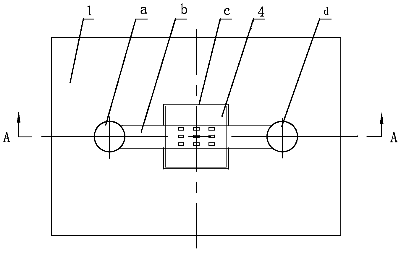
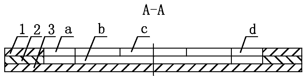
[0014] Such as figure 1 , 2 As shown, the bipolar electrode electrochemiluminescence imaging electrolytic cell of this embodiment is composed of an upper substrate 1, a middle substrate 2, and a lower substrate 3 connected together.

[0015] The upper surface of the lower substrate 3 is glued with the middle substrate 2, and the upper surface of the middle substrate 2 is glued with the upper substrate 1. The upper substrate 1, the middle substrate 2, and the lower substrate 3 are organic Glass sheet. An electrolytic cell c is processed at the center of the upper substrate 1. The structure of the electrolytic cell c is a square groove, the bottom of the square groove is the middle substrate 2, and the side length of the square groove is 8.5mm. A channel b is processed at the center of the middle substrate 2. The shape of the channel b is a rectangular groove, the bottom of the rectangular groove is the lower substrate 3, the length of the rectangular groove is 20...

Example Embodiment

[0016] Example 2

[0017] The structure of the electrolytic cell c is a square groove, the side length of the square groove is 6mm, the shape of the channel b is a rectangular groove, the length of the rectangular groove is 16mm, the width is 2mm, and the shape of the left storage tank a is circular The groove, the diameter of the circular groove is 4mm, and the structure of the right liquid storage tank d is exactly the same as that of the left liquid storage tank a. Other parts and the connection relationship of the parts are the same as in the first embodiment.

Example Embodiment

[0018] Example 3

[0019] The structure of the electrolytic cell c is a square groove, the side length of the square groove is 9mm, the shape of the channel b is a rectangular groove, the length of the rectangular groove is 22mm, the width is 3mm, and the shape of the left storage tank a is circular The groove, the diameter of the circular groove is 5mm, and the structure of the right liquid storage tank d is exactly the same as that of the left liquid storage tank a. Other parts and the connection relationship of the parts are the same as in the first embodiment.


PUM

PropertyMeasurementUnit
Side lengthaaaaaaaaaa
Diameteraaaaaaaaaa
Diameteraaaaaaaaaa

Abstract

A bipolar-electrode electrochemiluminescence imaging electrolytic cell adopts the structure that a middle substrate is stuck to the upper surface of a lower substrate through glue; an upper substrate is stuck to the upper surface of the middle substrate through glue; the upper substrate, the middle substrate and the lower substrate all adopt organic glass sheets; an electrolytic cell c is processed in the center of the upper substrate; the middle substrate is arranged at the bottom of the electrolytic cell c; a channel b is processed in the centers of the upper and middle substrates; the lower substrate is arranged at the bottom of the channel b; a left liquid storage tank a is processed at the left end of the channel b in the upper and middle substrates, and a right liquid storage tank d is processed at the right end of the channel b in the upper and middle substrates; the channel b is communicated with the left liquid storage tank a and the right liquid storage tank d. The bipolar-electrode electrochemiluminescence imaging electrolytic cell has the advantages of reasonable design, simple structure and reusability, can adopt either an upright microscope or an inverted microscope, and can be popularized and applied in bipolar-electrode electrochemiluminescence imaging analysis.

Description

technical field [0001] The invention belongs to the technical field of electrochemiluminescence equipment or devices, and in particular relates to a field-induced electrochemiluminescence electrolytic cell utilizing the electric field enrichment effect of double electrodes. Background technique [0002] A bipolar electrode is a conductor not connected to an external power source but placed in the electrolyte between the driven cathode and anode. When a sufficiently strong electric field is applied to the electrolyte solution, even if the conductor is not directly electrically connected to the external power source, the Faraday reaction can occur simultaneously at both ends of the conductor, and the oxidation reaction occurs at the end close to the driving cathode, called the anode, The reduction reaction occurs near the end of the driving anode, which is called the cathode. Electrochemiluminescence is a kind of light radiation produced by applying a certain voltage on the e...

Claims


Application Information

Patent Timeline
IPC IPC(8): G01N27/28G01N21/76
Inventor 张成孝孙丽娟漆红兰阮三鹏杜滢鑫
Owner SHAANXI NORMAL UNIV
Why Eureka
Try Eureka