
Verilog coding method achieving ATE test waveform by adoption of FPGA
Patent Information
- Authority / Receiving Office
- CN · China
- Patent Type
- Applications(China)
- Current Assignee / Owner
- Publication Date
- 2014-08-06
- Estimated Expiration
- Not applicable · inactive patent
Smart Images
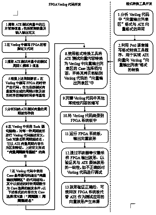
Figure 1 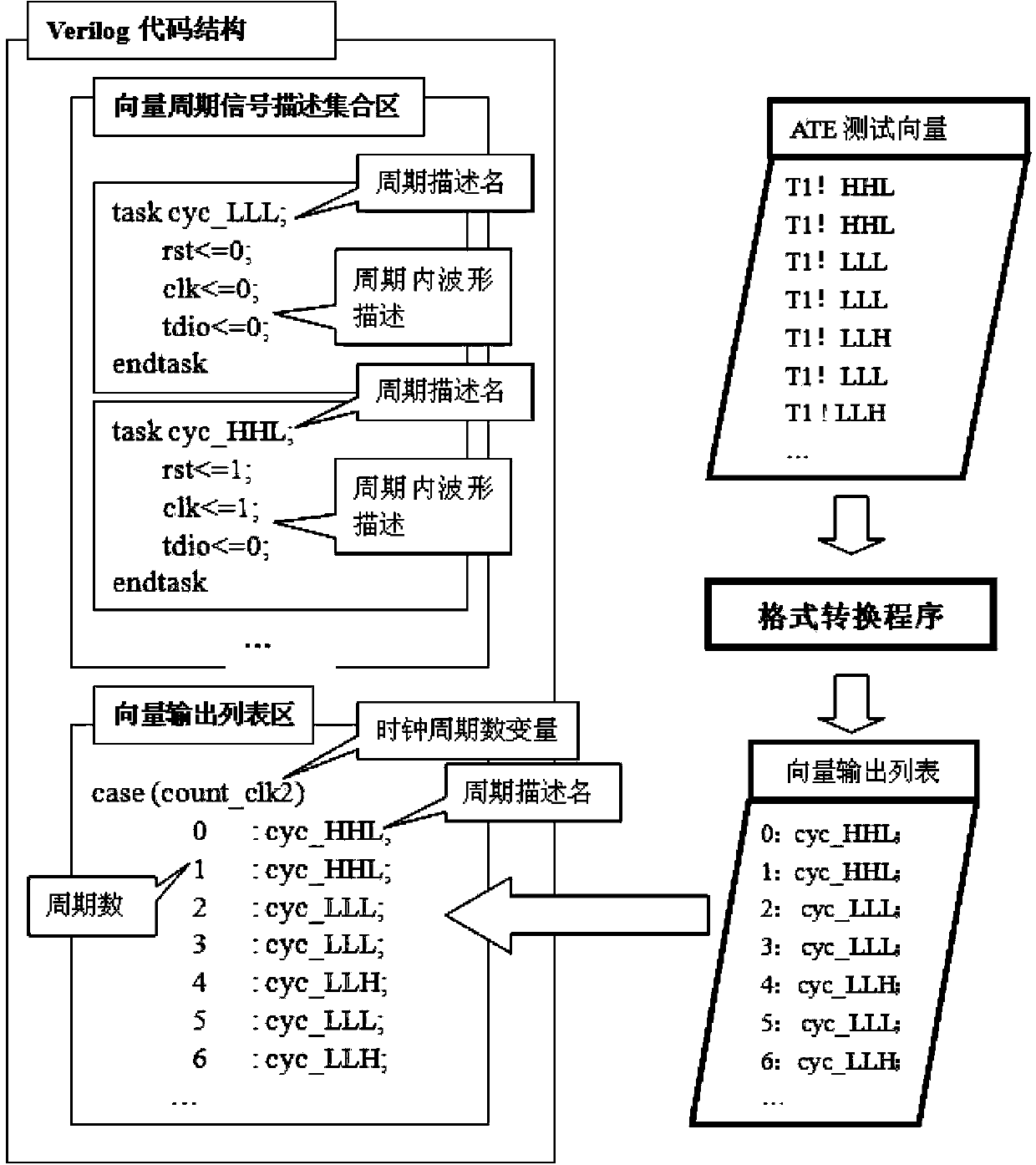
Figure 2
Abstract
Description
technical field
[0001] The invention relates to the field of semiconductor manufacturing, in particular to a Verilog encoding method for implementing ATE test waveforms using FPGA. Background technique
[0002] FPGA (Field Programmable Gate Array) is usually used for circuit design verification or product customization. Due to its powerful ability to design and implement logic functions, in the field of testing, FPGA is also used to generate specific test waveform vectors to replace professional test systems to implement some test applications. In the application of replacing ATE (automatic test equipment) to realize test waveform output, it is necessary to convert ATE test vector into FPGA design output through hardware description language. The ATE vector waveform has the characteristics of no logical relationship based on the clock cycle and inter-cycle signals. The traditional FPGA hardware description method based on the circuit function description does not reflect th...
Examples
Embodiment Construction
[0016] In an application, it is necessary to apply any excitation vector signal waveform to any integrated circuit chip in an environment far away from the ATE to make it enter the corresponding circuit action state. Due to the movable limitation of ATE, we need to use FPGA instead of ATE to complete the above excitation vector waveform to achieve the application purpose.
[0017] The method described in this invention was utilized in the development of FPGA vector generation in this application. figure 2 The application example is disclosed. In this application example, first analyze the ATE test vector to be applied, extract the required number of signal pins in the vector, and then define and describe the signal pins in the Verilog code. Then, the test cycle information used in the ATE vector is further extracted. According to the cycle information, a reference clock is designed in the Verilog code, which is used as the time reference for the cycle count and waveform timi...