Detector of magnetic bias, magnetic saturation, or amount of magnetic flux

A detector and magnetic bias technology, applied in the field of detectors, can solve problems such as the reduction of transformer core strength

Active Publication Date: 2014-08-06
DENSO CORP
View PDF6 Cites 10 Cited by
  • Summary
  • Abstract
  • Description
  • Claims
  • Application Information

AI Technical Summary

Problems solved by technology

Because this iron core is fragile, when the transformer iron core is provided ...

Method used


Image

  • Detector of magnetic bias, magnetic saturation, or amount of magnetic flux
  • Detector of magnetic bias, magnetic saturation, or amount of magnetic flux
  • Detector of magnetic bias, magnetic saturation, or amount of magnetic flux

Examples


no. 1 example )

[0049] [Configuration]

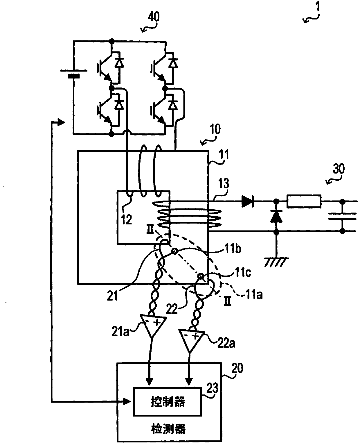
[0050] The configuration of the isolated power supply 1 according to the first embodiment of the present disclosure will be described. Such as figure 1 As shown, the isolated power supply 1 includes an inverter circuit 40 , a transformer 10 , a rectifier circuit 30 , and a detector 20 for detecting magnetic bias or saturation at the magnetic core 11 of the transformer 10 .

[0051] The inverter circuit 40 includes a power switching element, and generates a periodically varying rectangular-wave AC voltage from a DC voltage generated by a DC power source. The transformer 10 converts the amplitude of the AC voltage generated from the inverter circuit 40 . The transformer 10 includes a magnetic core 11 , a primary winding 12 and a secondary winding 13 . The magnetic core 11 is shaped as a rectangular ring structure. The primary winding 12 is supplied with an AC voltage. The secondary winding 13 outputs the converted voltage.

[0052] The magnetic cor...

no. 2 example )

[0220] [Configuration]

[0221] The configuration of an isolated power supply 1 according to a second embodiment of the present disclosure will be described. The isolated power supply 1 according to the second embodiment differs from the first embodiment in the configuration of the detection winding.

[0222] Such as Figure 27 As shown, the second embodiment forms a hole 11h at the corner 11a of the magnetic core 11 of the transformer 10. The hole 11h penetrates the corner 11a from the upper surface to the lower surface. A wire is inserted into the hole 11h and wound in the shape of an 8 around the corner 11a to configure a dual detection winding 28 .

[0223] Specifically, such as Figure 28 As shown, the non-uniform section 11i (along Figure 27 A section taken along the line XXVIII-XXVIII in ) is formed along the hole 11h in the corner 11a. The hole 11h divides the non-uniform section 11i into two regions, namely, a first region 11ix positioned toward the inside and ...

no. 1 example

[0245] Next, magnetic saturation elimination processing according to the second embodiment will be described. The total induced voltage is equal to the difference between the inner induced voltage and the outer induced voltage. Therefore, similar to the first embodiment, it is possible to detect excessive magnetic saturation based on a change in the total induced voltage, and to stop the application of the voltage to the primary winding 12 .

[0246] Similar to the internally induced voltage, the total induced voltage varies with the magnetic flux passing through the core 11 And change. when flux Hours, a large total induced voltage is induced. when flux When large, a small total induced voltage is induced. Therefore, the first magnetic saturation elimination processing can be performed similarly to the first embodiment.

[0247] However, if the magnetic flux Large enough, the total induced voltage can become negative. In this case, in Figure 23 In the S450, the ...


PUM


Abstract

A detector includes a detection winding (21, 22, 27, 28), a detection winding measurement section (24), and a detection section (23). A magnetic core (11, 61, 71, 81, 92) has a hole (11b, 11cm 11e, 11f, 11g, 11h, 61d, 61e, 71b, 81b, 92b) penetrating the magnetic core along a non-uniform cross section. The detection winding includes a wire inserted into the hole and surrounding a periphery of a detection region (11dx, 11dy, 11ix, 11iy) that is a part of the non-uniform cross section and has a magnetic flux density different from an average magnetic flux density of the non-uniform cross section. The detection winding measurement section performs a measurement relating to an electromotive force induced by the detection winding. The detection section detects a magnetic bias, a magnetic saturation, or an amount of magnetic flux in the magnetic core based on a measurement result of the detection winding measurement section.

Description

technical field [0001] The present disclosure relates to detectors that detect magnetic bias, magnetic saturation, or magnetic flux in a magnetic core. Background technique [0002] The isolated power supply is provided with a transformer for electrically isolating the input side and the output side. However, if too much magnetic bias is present in the transformer's core, losses can increase, or the core can become magnetically saturated causing excessive field current in the windings. Necessary solutions to this problem include controlling the voltage and detecting magnetic bias or excess DC flux generated in the magnetic core to eliminate magnetic bias and magnetic saturation. [0003] In the magnetic bias evaluation device described in JP-A-H11-40429, the magnetic core of the transformer is provided with a small π-type magnetic core (bypass magnetic circuit) made of a material with higher magnetic permeability than the magnetic core. In addition, the bypass magnetic cir...

Claims


Application Information

Patent Timeline
IPC IPC(8): G01R33/02H01F27/24
CPCG01R33/02G01R33/1215
Inventor 梅谷和弘
Owner DENSO CORP
Why Eureka
Try Eureka