Magnetic field sensor

A magnetic field sensor and magnetic core technology, applied in the field of magnetic field sensors, can solve the problems of reducing the operating frequency range of distributed capacitance sensors, not considering the influence of sensor measurement, not considering electric field shielding measures, etc., and achieving light weight, increased distance, and volume. small effect

Active Publication Date: 2014-08-06
INST OF ELECTRONICS CHINESE ACAD OF SCI
View PDF6 Cites 10 Cited by
  • Summary
  • Abstract
  • Description
  • Claims
  • Application Information

AI Technical Summary

Problems solved by technology

[0005] (1) The influence of the eddy current in the magnetic core on the measurement of the sensor is not considered. During the observation by the transient electromagnetic method, due to the alternating change of the primary field, the sensor is in an environment where the magnetic field changes drastically, and an induced eddy current will be generated in the magnetic core 1 , the eddy current will generate a magnetic field that interferes with the sensor measurement
[0006] (2) Measures are not taken to suppress the distributed capacitance of the sensor coil 2. The distributed capacitance of the coil 2 limits the working frequency band of the sensor. Reducing the distributed capacitance can expand the working frequency range of the sensor
[0007] (3) Electric field shielding measures are not considered. CN100456047C only uses circuit shielding measures for the amplifier circuit 3. Permalloy is used as shielding in CN10347290A. Permalloy is a magnetic material and a good conductor, which not only shields the electric field but also attenuates the magnetic field that needs to be measured signal, and the overall shielding layer 8 also has a current loop, which will generate an eddy current magnetic field that affects the measurement

Method used


Image

  • Magnetic field sensor
  • Magnetic field sensor
  • Magnetic field sensor

Examples


Embodiment Construction

[0024] In order to make the object, technical solution and advantages of the present invention clearer, the present invention will be further described in detail below in conjunction with specific embodiments and with reference to the accompanying drawings.

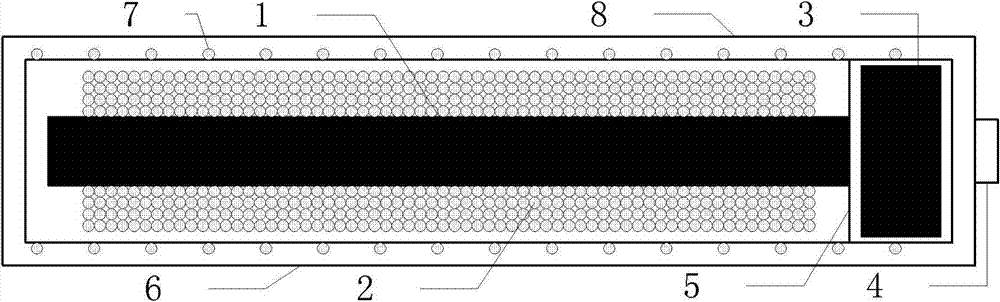
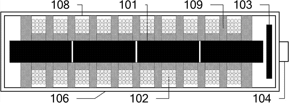
[0025] figure 2 A schematic structural diagram of a magnetic field sensor proposed by the present invention is shown. Such as figure 2 shown, which includes:

[0026] The segmented magnetic core 101 is placed in the hollow part of the hollow skeleton 109. It is a cylindrical structure and is formed by bonding multiple segments of equal-length magnetic materials. Considering the high magnetic permeability and electrical conductivity of the magnetic core material, it is preferably ferrite Material, the conductivity of ferrite is low, only 0.2x10⁻⁵S / m, it is an insulator, and it is better than magnetic materials such as permalloy with high conductivity.

[0027] Using multi-sections of ferrite of equal length to bond in...


PUM


Abstract

The invention discloses a magnetic field sensor which comprises a shell which is in a cylindrical structure, a hollow skeleton which is a hollow columnar body, a segmented magnetic core, multiple sections of coils and an amplifying circuit, wherein the outer surface of the hollow skeleton is provided with a plurality of same annular grooves at equal spacings; the segmented magnetic core is arranged in a hollow part of the hollow skeleton and is formed by connecting multiple sections of magnetic core materials equal in length; the multiple coils respectively winds in the annular grooves of the hollow skeleton and are serially connected to the amplifying circuit; the amplifying circuit is arranged at one end in the shell and used for amplifying and outputting induction signals of the multiple coils. According to the magnetic field sensor disclosed by the invention, a working band is completely expanded and the influence of the sensor on magnetic field measurement is effectively reduced; moreover, the electric field interface of an environment surrounding is shielded and the accuracy of measuring magnetic field signals is guaranteed. The magnetic field sensor disclosed by the invention is small in volume, light in weight, and effectively applicable to engineering application of a ground transverse electric and magnetic field (TEM).

Description

technical field [0001] The invention relates to the technical field of geophysical electromagnetic prospecting, in particular to a magnetic field sensor. Background technique [0002] Transient electromagnetic method, referred to as TEM, is an important method in geophysical electromagnetic prospecting methods, and is currently widely used in various underground resource exploration. At present, the TEM electromagnetic exploration instruments used in China are mainly products of foreign companies, such as the PREOTEM series of Geonics, the GDP-32 of Zonge, and the TerraTEM series of MonexGeoscope. The TEM instruments of each company have magnetic field sensors. There are also many domestic institutions developing TEM instruments, but there are few researches on the use of magnetic field sensors with the instruments. Can find the Chinese patent application CN1766674A magnetic component magnetic field sensor of Wang Jun of Jilin University etc., the Chinese patent application...

Claims


Application Information

Patent Timeline
Patent Type & Authority Applications(China)
IPC IPC(8): G01V3/10
Inventor 刘凯朱万华闫彬刘雷松方广有
Owner INST OF ELECTRONICS CHINESE ACAD OF SCI
Why Eureka
Try Eureka