Optical switch array based on DLP

An optical switch array and array technology, which is applied in the field of optical communication devices, can solve the problems of difficulty in adapting to the transmission requirements of the optical transmission network, slow speed of mechanical optical switches, and difficulty in large-scale integration, and achieves simple structure, fast channel switching speed, and volume. small effect

Inactive Publication Date: 2014-08-06
SHANGHAI BRANCH FUZHOU GAOYI COMM CO LTD
View PDF3 Cites 0 Cited by
  • Summary
  • Abstract
  • Description
  • Claims
  • Application Information

AI Technical Summary

Problems solved by technology

[0007] With the development of the Internet, higher requirements are placed on transmission speed and bandwidth. Traditional mechanical optical switches are slow, bulky, difficult to integrate on a large scale, and difficult to adapt to the TbiVs-level transmission requirements of optical transport networks. New microelectronic switches Micro-mechanical optical switches based on mechanical systems (Micro. Electro-Mechanical System, referred to as MEMS) have become the mainstream direction of the development of large-capacity switching optical network switches due to their small size and easy integration.

Method used


Image

  • Optical switch array based on DLP
  • Optical switch array based on DLP
  • Optical switch array based on DLP

Examples


Embodiment Construction

[0016] The present invention will be further described below in conjunction with the accompanying drawings and specific embodiments.

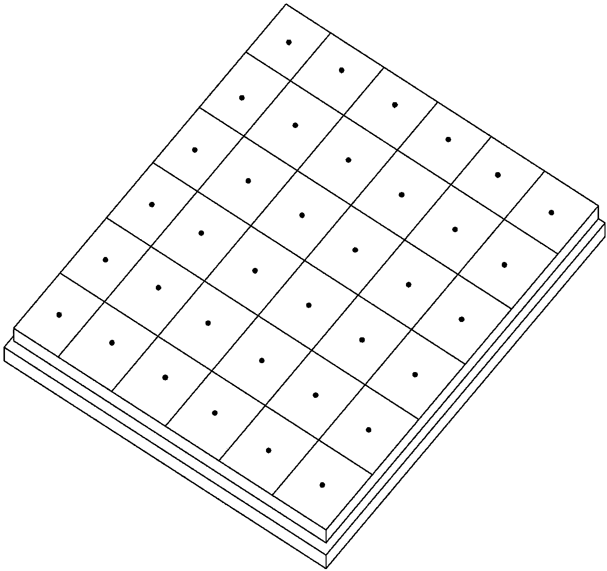
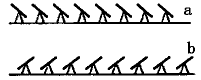
[0017] The core of the DLP (Digital Light Procession) digital light processor used in the present invention is a digital micromirror device DMD (Digital Micromirror Device) developed by TI (Texas Instruments). DMD is an array of extremely small mirrors (a few microns to a dozen microns). These micro mirrors are suspended and can be tilted to both sides by about 10~12 degrees, so as to form reflections in two directions, such as figure 1 and 2 As shown, the state of each micromirror can be independently controlled by DLP (Digital Light Processor).

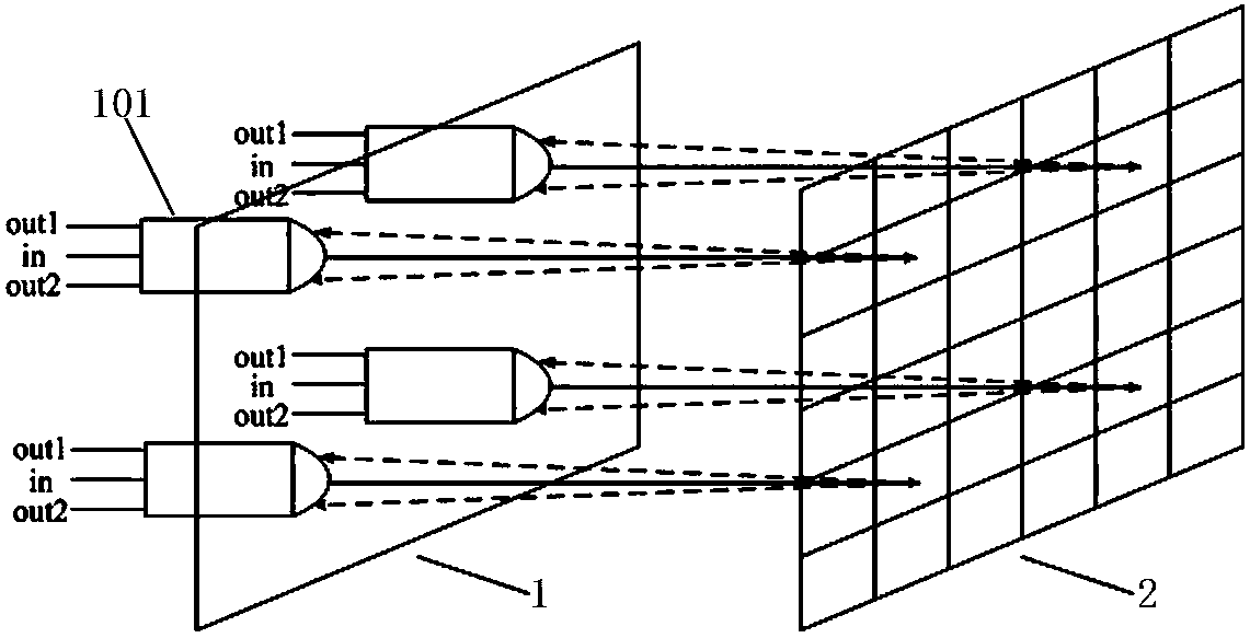
[0018] Such as image 3 Shown is a specific embodiment of the present invention, a DLP-based optical switch array, including an input-output cell array 1 and a DLP 2; each micromirror of the DLP 2 has two working states of deflection directions; the input-output cell array 1 is arranged In front o...


PUM


Abstract

The invention relates to the field of optical communication devices, and discloses an optical switch array based on a DLP. The optical switch array based on the DLP comprises an input and output unit array and the DLP, wherein each micro reflector mirror of the DLP has the work states of two defecting directions, the input and output unit array is arranged in front of the DLP, each input and output unit is provided with one input port and two output ports, input light of the input ports is emitted to different areas of a micro reflector mirror array of the DLP, and the two deflecting directions of the micro reflector mirrors of the DLP respectively reflect corresponding incident light back to the two output ports of the original input and output unit. Multiple 1*2 optical switch units share one DLP and respectively emit the input light to the different areas of the micro reflector mirror array of the DLP, and a 1*2 optical switch distributed in an array mode is achieved. The number of the units of the optical switch array can be properly increased according to needs and the size of the DLP, and the optical switch array based on the DLP has the advantages of being simple in structure, high in integration degree, small in size, high in channel switch speed and the like.

Description

technical field [0001] The invention relates to the field of optical communication devices, in particular to a DLP-based optical switch array. Background technique [0002] The advent and development of optical fiber communication technology has brought revolutionary changes to the communication industry. At present, about 85% of the world's communication services are transmitted through optical fibers, and optical fibers have also been widely used in long-distance trunk networks and local relay networks. At the same time, the development and maturity of dense wavelength division multiplexing (DWDM: Dense Wavelength. Division Multiplexing) technology has opened up a broad space for the full application of the bandwidth and capacity of optical fiber transmission. Become the current development trend of communication network. Especially in recent years, Internet services mainly based on ports have shown explosive growth. This growth trend has not only changed the relationship...

Claims


Application Information

Patent Timeline
Patent Type & Authority Applications(China)
IPC IPC(8): G02B6/35
Inventor 张琥杰郑保忠李阳吴砺
Owner SHANGHAI BRANCH FUZHOU GAOYI COMM CO LTD
Why Eureka
Try Eureka