Method and equipment for manufacturing separated type RFID (radiofrequency identification) tags for antennas

A technology for RFID tags and manufacturing methods, applied to antennas, antenna parts, antenna supports/installation devices, etc., can solve the problems of large antenna distance, waste of raw materials, waste of raw materials, etc., and achieve less waste discharge and lower Effects of material loss and shortened travel distance

Inactive Publication Date: 2014-08-06
SHENZHEN HYAN MICROELECTRONICS
View PDF4 Cites 12 Cited by
  • Summary
  • Abstract
  • Description
  • Claims
  • Application Information

AI Technical Summary

Problems solved by technology

[0003] Regardless of whether the antenna is made of etched copper / aluminum foil or die-cut copper / aluminum foil, the distance between the antennas is also very large to meet the requirements of the equal spacing of the labels. waste
Due to the large distance between the antennas, there is a large amount of blank space, and the efficiency loss is also considerable when produced on a placement machine.

Method used


Image

  • Method and equipment for manufacturing separated type RFID (radiofrequency identification) tags for antennas
  • Method and equipment for manufacturing separated type RFID (radiofrequency identification) tags for antennas
  • Method and equipment for manufacturing separated type RFID (radiofrequency identification) tags for antennas

Examples


Embodiment Construction

[0039] The present invention will be described in detail below in conjunction with the embodiment of the split antenna RFID tag and the device.

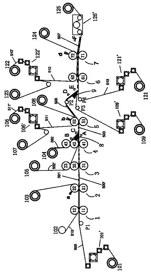
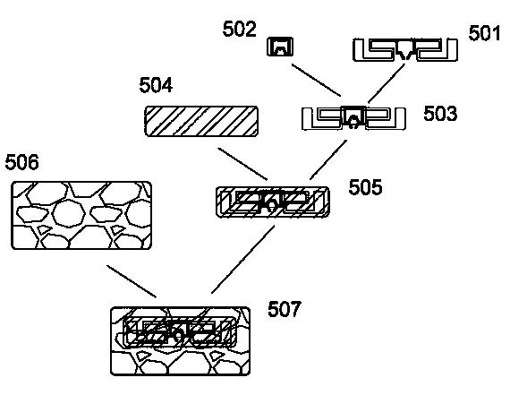
[0040] figure 2 The embodiment of the split antenna RFID tag mainly includes four parts: a die-cut aluminum foil antenna 501, an RFID unit 502, a PET film 504 and a face paper 506, which are stacked sequentially from bottom to top to form a split antenna RFID tag.

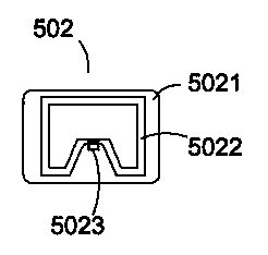
[0041] Such as image 3 , the RFID unit 502 includes a base film 5021, a radiation antenna 5022 printed on the base film, and a radio frequency IC5023; the radiation antenna 5022 is generally square, and the lower side is bent inward to form an inner concave part of the middle opening, and the radio frequency IC5023 is connected to the opening place. The RFID unit 502 can be manufactured using traditional techniques, with adhesive on the back and attached to the base tape 502' with a certain step distance L2, and the base tape 502' adopts a release tape such as a relea...


PUM


Abstract

The invention discloses a method and equipment for manufacturing separated type RFID (radiofrequency identification) tags for antennas. The method includes S1, enabling a drive shaft (21) and a drive shaft (51) of a first conveying mechanism to drive a carrier tape with an aluminum foil to convey the aluminum foil at the speed of V1; compositing an adhesive tape with the carrier tape with the aluminum foil, and performing die cutting on the adhesive tape and the carrier tape with the aluminum foil by the aid of an antenna circular cutting die (22) to obtain aluminum foil antennas; S2, conveying a base tape with RFID units at variable speeds in certain periods, separating the RFID units from the base tape when the base tape passes a flat scraper, and adhering the RFID units on the upper surfaces of the corresponding aluminum foil antennas on the carrier tape to form tag modules; S3, enabling the drive shaft (51) to drive a PET (polyethylene terephthalate) film with gum, performing die cutting on the PET film with the gum by the aid of a PET film circular cutting die (52) to form PET films, and enabling the PET films to cover the corresponding tag modules on the upper surface of the carrier tape to form semi-finished products. The antenna circular cutting die (22) is arranged at the edge of the drive shaft (21), and the PET film circular cutting die (52) is arranged at the edge of the drive shaft (51). The method and the equipment have the advantages that the equipment is provided with a plurality of conveying mechanisms, the conveying mechanisms are controlled by a master control unit, accordingly, repeated compositing, die cutting, waste discharging and secondary asynchronous aligning, transferring and labeling operation can be completed, and various separated type tag products can be automatically produced.

Description

technical field [0001] The invention relates to a manufacturing technology of an electronic tag, in particular to a manufacturing method of a split-antenna RFID tag and equipment used therefor. Background technique [0002] At present, most RFID manufacturing equipment adopts synchronous technology, that is, based on the size and spacing of customer tags, the antenna spacing is the same as that of customer tags. Even if multi-equipment linkage is adopted, each process such as placement, die-cutting, and alignment compounding is carried out simultaneously and at the same speed under the condition of equal spacing. [0003] Regardless of whether the antenna is made of etched copper / aluminum foil or die-cut copper / aluminum foil, the distance between the antennas is also very large in order to meet the requirements of the equal spacing of the labels. waste. Due to the large distance between the antennas, there is a large amount of blank space, and the efficiency loss is also c...

Claims


Application Information

Patent Timeline
Patent Type & Authority Applications(China)
IPC IPC(8): G06K19/07H01Q1/22B26F1/38B65H37/04
CPCB26F1/384G06K19/07718G06K19/07773G06K19/07786H01Q1/2225Y10T156/1052B65H37/002B65H37/04G06K19/0723H01Q1/2208H01Q23/00
Inventor 滕玉杰张世凡滕玉东
Owner SHENZHEN HYAN MICROELECTRONICS
Why Eureka
Try Eureka