Helicopter antenna

A technology for helicopters and antennas, applied in the direction of antenna support/installation device, radiation element structure, radiation unit cover, etc., can solve the problems of unable to change the antenna radiation elevation angle, reduce antenna reliability, reduce communication distance, etc., to eliminate Effects of dithering noise and broken wires, improving antenna patterns, and solving dead zone problems

Inactive Publication Date: 2014-08-06
陕西烽火诺信科技有限公司
View PDF4 Cites 3 Cited by
  • Summary
  • Abstract
  • Description
  • Claims
  • Application Information

AI Technical Summary

Problems solved by technology

[0005] 2 Radiation elevation angle is small, with communication blind area
[0006] It can be seen from the principle of the antenna that the 3dB bandwidth of the radiation pattern of the antenna (this indicator determines the radiation elevation angle of the antenna) is fixed, and the antenna radiation elevation angle cannot be changed by changing the diameter and length of the antenna, so there is a communication dead zone in the axial direction of the antenna
[0007] 3. With jitter noise, broken wire phenomenon
Antenna jitter will generate jitter noise, which will be transmitted to

Method used


Image

  • Helicopter antenna
  • Helicopter antenna
  • Helicopter antenna

Examples


Embodiment Construction

[0033] In order to make the object, technical solution and advantages of the present invention clearer, the present invention will be further described in detail below in conjunction with specific embodiments and with reference to the accompanying drawings. It should be understood that these descriptions are exemplary only, and are not intended to limit the scope of the present invention. Also, in the following description, descriptions of well-known structures and techniques are omitted to avoid unnecessarily obscuring the concept of the present invention.

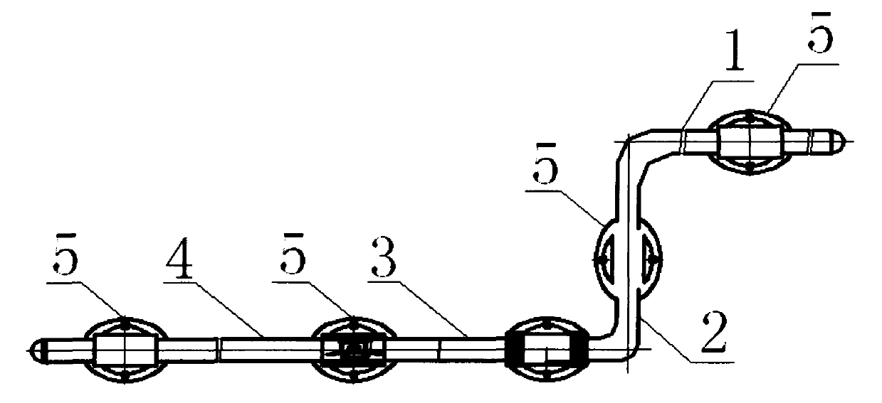
[0034] figure 1 It is a structural schematic diagram of a helicopter antenna in the present invention, specifically including antenna tube one 1, antenna tube two 2, antenna tube three 3, antenna tube four 4 and a support frame 5. Among them, antenna tube one 1, antenna tube two 2, antenna tube three 3, and antenna tube four 4 are connected through a plug-in structure to form an integrated "Z" shape, and then the support...


PUM

PropertyMeasurementUnit
Pitchaaaaaaaaaa
Diameteraaaaaaaaaa
Widthaaaaaaaaaa

Abstract

A helicopter antenna is characterized in that the antenna is of a 'Z'-shaped tube shape, a spiral radiator is disposed inside the antenna, and the working frequency band of the antenna is 2MHz-30MHz. The helicopter antenna has the advantages that on the basis of guaranteeing the performance of the antenna, the length of the antenna is reduced, the directivity angle of the antenna is increased, jitter noise and wire fracture are reduced, and influence of freezing on the antenna is reduced.

Description

technical field [0001] The invention relates to the technical field of antennas, in particular to a helicopter antenna. Background technique [0002] At present, most of the airborne antennas used in the short-wave (HF) frequency band in my country's helicopter communication system are cable antennas. This type of antenna has the following shortcomings and problems to be solved: [0003] 1. The size is too long [0004] The cable antenna is a single-stage sub-antenna that relies on the resonance of the cable whose electrical length is 1 / 4 of the signal wavelength. Because the wavelength of the short-wave frequency band is longer, the antenna length is relatively large. [0005] 2 Radiation elevation angle is small, with communication blind zone [0006] It can be seen from the principle of the antenna that the 3dB bandwidth of the radiation pattern of the antenna (this indicator determines the radiation elevation angle of the antenna) is fixed, and the antenna radiation el...

Claims


Application Information

Patent Timeline
IPC IPC(8): H01Q1/36H01Q1/12H01Q1/42
Inventor 张志云于汶涛卢攀张伟东魏宁强任利媛
Owner 陕西烽火诺信科技有限公司
Why Eureka
Try Eureka