Parameter sending method and device and uplink demodulation reference signal emission method and device

A technology for demodulating reference signals and sending methods, which is applied in the field of wireless communication, can solve problems such as limiting network capacity improvement, application or performance-limited user movement speed, etc., and achieves the effect of improving the quality of channel estimation

Active Publication Date: 2014-08-06
ZTE CORP
View PDF4 Cites 52 Cited by
  • Summary
  • Abstract
  • Description
  • Claims
  • Application Information

AI Technical Summary

Problems solved by technology

[0006] 1. The maximum number of multiplexing users supported is two, which limits the further improvement of network capacity;
[0007] 2. This method can only be used when the coherence time of the channel is greater than the time domain span of a subframe (including two slots), that is, its application or performance is limited by the user's moving speed

Method used


Image

  • Parameter sending method and device and uplink demodulation reference signal emission method and device
  • Parameter sending method and device and uplink demodulation reference signal emission method and device
  • Parameter sending method and device and uplink demodulation reference signal emission method and device

Examples


Embodiment Construction

[0083] The technical solutions of the present invention will be further elaborated below in conjunction with the accompanying drawings and specific embodiments.

[0084] A method for sending parameters provided by an embodiment of the present invention, such as Figure 5 As shown, it mainly includes:

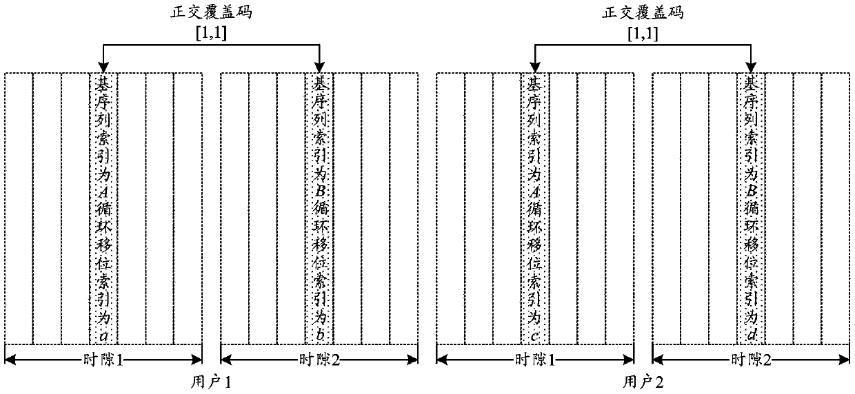
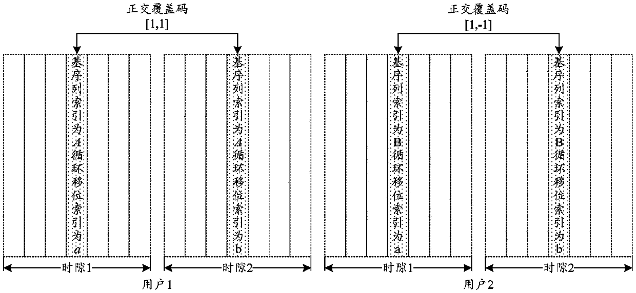
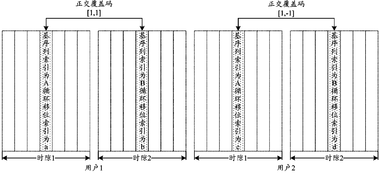
[0085] In step 501, the network side allocates parameters for generating DMRS sequences to the user side, and the parameters include: system bandwidth, resource block index, cyclic shift index and DMRS base sequence index.

[0086] Step 502, the network side sends the generated parameters to the user side.

[0087] In the embodiment of the present invention, the network side mainly refers to a base station, and the user side mainly refers to a user terminal (UE).

[0088] Wherein, the network side assigns a cyclic shift index to the user side, including:

[0089] A. Divide cyclically shifted user clusters according to all user resource block indexes. The cyclically shifted us...


PUM


Abstract

The invention discloses a parameter sending method and device. The method comprises the steps that a network side distributes parameters used for generating DMRS sequences of demodulation reference signals to a user side, the parameters comprise system bandwidth, resource block indexes, circulating shift indexes and DMRS basic sequence indexes, and the network side sends the generated parameters to the user side. The invention further discloses an uplink demodulation reference signal emission method and device. The method comprises the steps that the user side receives the parameters sent by the network side and used for generating the DMRS sequences, the parameters comprise the system bandwidth, the resource block indexes, the circulating shift indexes and the DMRS basic sequence indexes, and the user side determines the corresponding DMRS sequences according to the received parameters and transmits the DMRS sequences on corresponding physical resources. According to the method and the device, DMRS orthogonality of more than two users with the bandwidth parts overlapped can be supported, and application and performance are not limited by the moving speed of the users.

Description

technical field [0001] The present invention relates to signal transmission technology in the field of wireless communication, in particular to a parameter transmission method and device, and an uplink demodulation reference signal (DMRS, Demodulation Reference Signal) transmission method and device. Background technique [0002] The Long Term Evolution (LTE, Long Term Evolution) project is the evolution of the third generation mobile communication technology (3G, Third Generation), it is a transition between 3G and the fourth generation mobile communication technology (4G, FourthGeneration), it improves and Enhanced 3G air access technology, using Orthogonal Frequency Division Multiplexing (OFDM, Orthogonal Frequency Division Multiplexing) technology and Multiple Inputs and Multiple Outputs (MIMO, Multiple Inputs and Multiple Outputs) technology (ie, multi-antenna technology) as wireless network evolution the only standard. Long-Term Evolution-Advanced (LTE-A, LTE-Advanced...

Claims


Application Information

Patent Timeline
Patent Type & Authority Applications(China)
IPC IPC(8): H04L1/00H04L1/06H04L27/26
Inventor 陈宪明罗薇关艳峰
Owner ZTE CORP
Why Eureka
Try Eureka