Base station antenna feed network

A technology of feed network and base station antenna, which is applied in the field of feed network, can solve the problems of poor electrical performance and consistency of products, complex structure of feed network, and increased volume of phase shifters, etc., to achieve small size and avoid signal Leaky, compact effect

Active Publication Date: 2014-08-06
TONGYU COMM INC
View PDF3 Cites 26 Cited by
  • Summary
  • Abstract
  • Description
  • Claims
  • Application Information

AI Technical Summary

Problems solved by technology

[0003] A phase shifting device in the traditional technology uses a metal conductor rod to move back and forth in a metal conductor tube to change the actual length of the transmission path to achieve the purpose of phase change, but in actual use, an external power divider must be added for power distribution, and In order to obtain a large amount of phase shift, it is generally necessary to increase the volume of the phase shifter, which leads to a complex structure of the feed network, and the electrical performance and consistency of the product will also deteriorate
Another kind of equal-phase differential multi-channel composite phase shifter in the prior art adopts microstrip type power splitter and phase shifter, especially the line length adjustment mechanism of the phase shifter, which has large loss and unstable performance. Obviously insufficient, less used in mass production
[0004] Therefore, the feed network of the prior art has disadvantages and problems such as cumbersome structural assembly, many solder joints, large power loss, poor consistency, large volume, and high manufacturing cost.

Method used


Image

  • Base station antenna feed network
  • Base station antenna feed network
  • Base station antenna feed network

Examples


Embodiment Construction

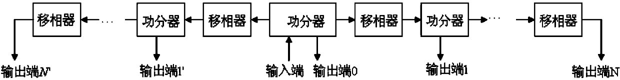
[0027] see figure 1 , the base station antenna feeding network of the present invention includes a one-point three-power divider, and the power input by the feed port is divided into three paths through the one-point three-power divider, one of which is used to feed power to the array center unit, and the other two outputs connected to the phase shifters at the left and right ends, and the adjacent phase shifters are cascaded through one-two power dividers to feed power to the units on the left and right sides of the array respectively. figure 1 There are N phase shifters, N-1 one-two power splitters, N' phase shifters, and N'-1 one-two power splitters on both sides of the one-point-three power splitter. The output terminal of the previous phase shifter is connected to the input terminal of the power divider, one output terminal of the power divider is used as an output terminal of the entire feed network, and the other output terminal is connected to the input terminal of the...


PUM


Abstract

The invention provides a base station antenna feed network which comprises at least two power dividers and at least three phase shifters. The output end of a front phase shifter is connected with the input end of a power divider. One output end of the power divider is used as one output end of the whole feed network, and the other output end is connected with the input end of a next phase shifter. Each phase shifter comprises a fixed transmission line and a slidable transmission line. The phase shifters and the power dividers are respectively arranged in an integrally formed metal chamber structure. Feed points are arranged along a long side direction. The base station antenna feed network according to the invention realizes flexible power dividing ratio design, stable performance and relatively low power loss. So that the feed network has advantages of compact structure, relatively small dimension, easy manufacture, low cost, easy realization for wide frequency band, more stable integral performance, higher consistency, and flexible combination for increasing number of output ends.

Description

technical field [0001] The invention relates to the field of mobile communication, in particular to a feeding network applied to an antenna of an electrically adjustable base station. Background technique [0002] With the development of mobile communication technology, the electrical and mechanical performance requirements of base station antennas are getting higher and higher, and its high performance and miniaturization have gradually become a development trend, such as larger electrical downtilt, higher efficiency, and wider bandwidth. Band, smaller size, etc., which put forward higher requirements on the performance of the base station antenna feed network. [0003] A phase shifting device in the traditional technology uses a metal conductor rod to move back and forth in a metal conductor tube to change the actual length of the transmission path to achieve the purpose of phase change, but in actual use, an external power divider must be added for power distribution, and...

Claims


Application Information

Patent Timeline
Patent Type & Authority Applications(China)
IPC IPC(8): H01Q23/00H01Q21/00H01Q1/24H01Q3/30
CPCH01Q21/0075H01P1/182H01P1/183H01P1/184H01P3/084H01P5/12H01Q3/32
Inventor 方锋明
Owner TONGYU COMM INC
Why Eureka
Try Eureka