Segmented type deburring roller

A segmented, deburring roller technology, applied in auxiliary devices, auxiliary welding equipment, welding/cutting auxiliary equipment, etc., can solve the problems of large impact force, affecting the service life of the deburring machine, inconvenient replacement, etc.

Inactive Publication Date: 2014-08-13
JIGANG GRP
View PDF8 Cites 5 Cited by
  • Summary
  • Abstract
  • Description
  • Claims
  • Application Information

AI Technical Summary

Problems solved by technology

When the deburring roller is working, the roller body rotates at high speed, and all the centrifugal throwing blocks on the same axis are thrown up and contact with the lower burr of the continuous casting slab at the same time. The impact force is huge at the moment of contact, and huge vibrat

Method used


Image

  • Segmented type deburring roller
  • Segmented type deburring roller

Examples


Embodiment Construction

[0018] In order to clearly illustrate the technical features of this solution, the specific implementation of the present invention will be further described below according to the accompanying drawings.

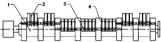
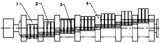
[0019] figure 1 A first embodiment of the invention is shown. Such as figure 1 As shown, a segmented deburring roller includes a roller body 1, a centrifugal throwing block 2, and a connecting shaft 3. A flange 4 is arranged on the roller body 1, and the flange 4 is a disc coaxial with the roller body 1. , the centrifugal rejection block 2 is a flat cuboid, the centrifugal rejection block 2 is provided with a through hole deviated from the center of the centrifugal rejection block 2, and the connecting shaft 3 passes through the through hole on the centrifugal rejection block 2 and is fixed on the flange 4; the centrifugal rejection block 2 The turning diameter when being thrown up is greater than the diameter of the flange 4; the axis of the connecting shaft 3 is parallel...


PUM


Abstract

The invention relates to a segmented type deburring roller. The segmented type deburring roller comprises a roller body, centrifugal swinging blocks and connecting shafts. Flanges are arranged on the roller body. Each centrifugal swinging block is provided with a through hole deviating from the center of the centrifugal swinging block. The connecting shafts penetrate through the through holes in the centrifugal swinging blocks and are fixed to the flanges. The rotation diameter, existing when each centrifugal swinging block is swung, of the centrifugal swinging block is larger than the rotation diameter, existing when each flange rotates, of the flange. The axis of each connecting shaft and the axis of the roller body are parallel to each other. One or more connecting shafts which are adjacent axially are grouped into one section. The connecting shafts of the same section are coaxial. The connecting shafts of every two adjacent sections are not coaxial. The segmented type deburring roller is small in vibration, low in noise, convenient to use, long in service life and capable of effectively eliminating oxidizing slag and burrs, left during flame cutting, of continuous casting sheet billets.

Description

technical field [0001] The invention relates to a deburring roller, in particular to a segmented deburring roller. Background technique [0002] The deburring machine is an indispensable equipment in the continuous casting slab production process in the iron and steel industry. The deburring roller is its main component. There are many centrifugal throwing blocks that can move freely on the roller body. During the high-speed rotation of the deburring roller, the centrifugal The block produces a huge impact force, and removes a large amount of oxide slag and burrs formed by the flame cutting of the lower part of the continuous casting slab. [0003] The deburring roller in the prior art includes a roller body, a centrifugal block, and a connecting shaft. A flange is arranged on the roller body, and a through hole deviated from the centrifugal block is provided on the centrifugal block, and the connecting shaft passes through the through hole on the centrifugal block. The hol...

Claims


Application Information

Patent Timeline
IPC IPC(8): B23P9/04B23K37/08
CPCB23P9/04B23K37/08
Inventor 张文周黄一声管延科徐振华田常松
Owner JIGANG GRP
Why Eureka
Try Eureka