Belt conveyer

A belt conveyor and frame technology, applied in the direction of conveyors, conveyor objects, transportation and packaging, etc., can solve the problems of increasing the rotating workload of the transmission roller, reducing the effective transmission volume, and damage to the conveyor belt, so as to avoid The effect of reducing transmission efficiency, improving working stability and increasing service life

Active Publication Date: 2014-08-13
承德光大输送机有限公司
View PDF7 Cites 2 Cited by
  • Summary
  • Abstract
  • Description
  • Claims
  • Application Information

AI Technical Summary

Problems solved by technology

[0004] In the long-term working state of the conveyor belt conveyor, more material residues will accumulate on the conveying surface of the conveyor belt, and the remaining materials will adhere to the conveying surface and rotate with the conveyor belt, which greatly increases the workload of the driving roller when it rotates. And the residual material will not slide down to the destination together with the material. While reducing the effective conveying capacity, it will also cause a certain degree of damage to the conveyor belt; at present, when cleaning the residual material on the surface of the conveyor belt, more use Alloy scraper, sticking it to the surface of the conveyor belt, under normal circumstances, this method can improve the cleaning effect, but when the main roller of the conveyor is in contact with the conveyor belt at the moment or the main roller fails and the conveyor belt stops suddenly, The conveyor belt will vibrate up and down to a certain extent, that is, it will move up and down. The scraper attached to the conveyor belt will directly generate force on the surface of the conveyor belt. When the main roller returns to normal, the scraper will directly rub against the conveyor belt, resulting in damage to the conveyor belt.

Method used


Image

  • Belt conveyer
  • Belt conveyer
  • Belt conveyer

Examples


Embodiment 1

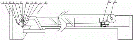
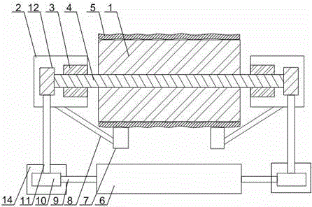
[0025] Such as Figure 1 to Figure 3As shown, a belt conveyor of the present invention includes a frame and a conveyor belt, on which a main roller 1, a driven roller 16 and a support cylinder 2 are arranged, and a conveyor belt 5 is sleeved on the main roller 1 and the driven roller 16, the rotating shaft 4 of the main drum 1 runs through one end of the supporting cylinder 2 and is rotated in the bearing 3, and the rotating shaft 4 is connected with the cylinder knife 6 parallel to the rotating shaft 4 through an interlocking mechanism; it also includes a V-shaped blade 7, so The V-shaped blade 7 is fixed on the support cylinder 2 through a connecting rod 8. The V-shaped blade 7 is in the shape of a circular arc matched with the outer surface of the main drum 1, and a roller 13 is installed on the intersection of the V-shaped blade 7. 13 is in contact with the conveyor belt 5 on the main drum 1, and a tensioning mechanism is installed on the driven drum 16. When the present ...

Embodiment 2

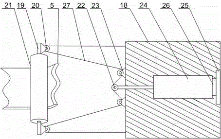
[0027] Such as image 3 As shown, on the basis of Embodiment 1, the present embodiment includes an adjustment platform 18, a support rod 19 and a pulling wire 27, and a roller 21 is rotated on the support rod 19, and at both ends of the support rod 19 A pulley 20 is installed, and the adjustment platform 18 is connected with the support rod 19 through the pulley 27 through the pulley 27. Cylinder 24 and baffle plate 25, pressure sensor 26 is installed between the tail end of cylinder 24 and baffle plate 25, and pressure sensor 26 is connected with the driving device of cylinder 24 by wire, on the flexible end of cylinder 24, rotating Wheel 22, runner 22 is connected with traction line 27, and traction line 27 is in tight state all the time during work. During work, the roller 21 is in contact with the non-transmitting surface of the conveyor belt 5, and the runner 22 cooperates with the pulley 20 through the traction line 27, so that the output end of the cylinder 24 is alway...

Embodiment 3

[0029] Such as figure 1 As shown, this embodiment is based on Embodiment 1, the interlocking structure includes a connecting rod 11, a large gear 12 and a pinion 10, the two ends of the rotating shaft 4 pass through the bearing 3, and the large gear 12 is installed on the rotating shaft 4 At both ends of the central axis 9 of the cylinder cutter 6, a protective cylinder 14 is installed, and a pinion 10 is arranged in the protective cylinder 14, and the end of the central axis 9 penetrates one side of the protective cylinder 14 and is connected with the pinion 10, so The two ends of the connecting rod 11 are equipped with racks, and the large gear 12 cooperates with the pinion 10 through the connecting rod 11 . The rotating shaft 4 rotates, and under the cooperation of the large gear 12, the pinion 10 and the connecting rod 11, the central shaft 9 will drive the cylinder knife 6 and the transmission drum 1 to rotate synchronously, so as to ensure that the cylinder knife 6 conta...


PUM


Abstract

The invention discloses a belt conveyer. The belt conveyer comprises a frame and a conveying belt; the frame is provided with a main roller, a driven roller and a support cylinder; the conveying belt sleeves the main roller and the driven roller; the rotating shaft of the main roller penetrates one end of the support cylinder and is rotatably arranged inside bearings and connected with a cylinder cutter, which is parallel to the rotating shaft, through a linkage mechanism. The belt conveyer also comprises a V-shaped blade which is fixed onto the support cylinder through a connecting rod, the V-shaped blade is in an arc shape matched with the outer surface of the main roller, the cross section of the V-shaped blade is provided with a wheel, and when in work, the wheel is in contact with the conveying belt on the main roller; the driven roller is provided with a tensioning mechanism. When the main roller fails and leads to vertical vibration of the conveying belt, the wheel mounted on the cross section of the V-shaped blade is in contact with the conveying belt, so that damage to the V-shaped blade due to too much contact between the V-shaped blade and the conveying surface of the conveying belt can be effectively avoided, and further the service life of the conveying belt can be prolonged.

Description

technical field [0001] The invention relates to a conveyor, in particular to a belt conveyor. Background technique [0002] The belt conveyor is a friction-driven machine that transports materials in a continuous manner. It can form a material conveying process on a certain conveying line from the initial feeding point to the final unloading point. It can not only transport broken materials, but also transport finished items; in addition to pure material transport, it can also cooperate with the requirements of the technological process in the production process of various industrial enterprises to form a rhythmic flow operation transport line. [0003] Belt conveyor is also called conveyor belt conveyor. The conveyor belt moves according to the principle of friction transmission. It is suitable for conveying powdery, granular and small pieces of low-grinding materials with a bulk density of less than 1.67 / ton / m3 and easy to dig out. Bagged materials, such as coal, gravel,...

Claims


Application Information

Patent Timeline
Patent Type & Authority Applications(China)
IPC IPC(8): B65G45/12B65G23/44B65G23/24
Inventor 陈志强
Owner 承德光大输送机有限公司
Why Eureka
Try Eureka