
Electrostatic spinning collection device and method, and electrostatic spinning equipment

An electrospinning and collecting device technology, applied in textiles and papermaking, filament/thread forming, fiber processing, etc., can solve the problems of disordered fibers, unsuitable for highly ordered organization, etc., and achieve the effect of high degree of fiber orientation

Inactive Publication Date: 2014-08-13
SHENZHEN GRADUATE SCHOOL TSINGHUA UNIV
View PDF7 Cites 16 Cited by
  • Summary
  • Abstract
  • Description
  • Claims
  • Application Information

AI Technical Summary

Problems solved by technology

[0004] The fibers electrospun by traditional electrospinning technology are messy and randomly distributed, and are mainly used in wound dressings, filtration barriers, transparent reinforcement materials, etc., which largely limits its application, especially in tissue engineering applications, because it is not suitable for building highly ordered organizations

Method used


Image

  • Electrostatic spinning collection device and method, and electrostatic spinning equipment
  • Electrostatic spinning collection device and method, and electrostatic spinning equipment
  • Electrostatic spinning collection device and method, and electrostatic spinning equipment

Examples


example 1

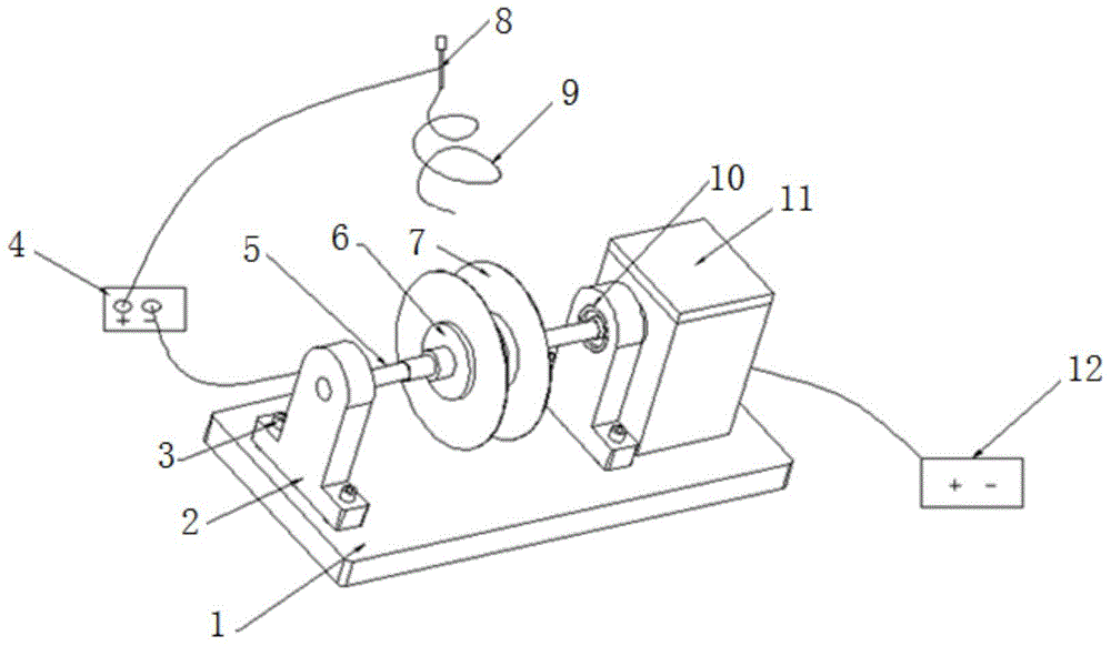
[0045] The uniaxial PVA fiber scaffold was electrospun using the above-mentioned device and method. The PVA concentration is 10%, the solution flow rate is set to 0.3ml / h, the voltage is 15KV, the distance between the needle tip of the syringe and the parallel thin disk is 175mm, the rotation speed of the thin disk is 500r / min, and the distance between the parallel thin disks is 38mm , the ambient temperature of electrospinning was 37. The rotatable planar fiber collector is fixed at a certain position, so that the circular collecting disc in the rotatable planar fiber receiving device is located between the two thin plates, and the circular collecting disc is kept stationary to collect oriented fibers in one direction. The electrospinning time was 3h. The obtained uniaxially oriented fibers are as Figure 4 shown.

example 2

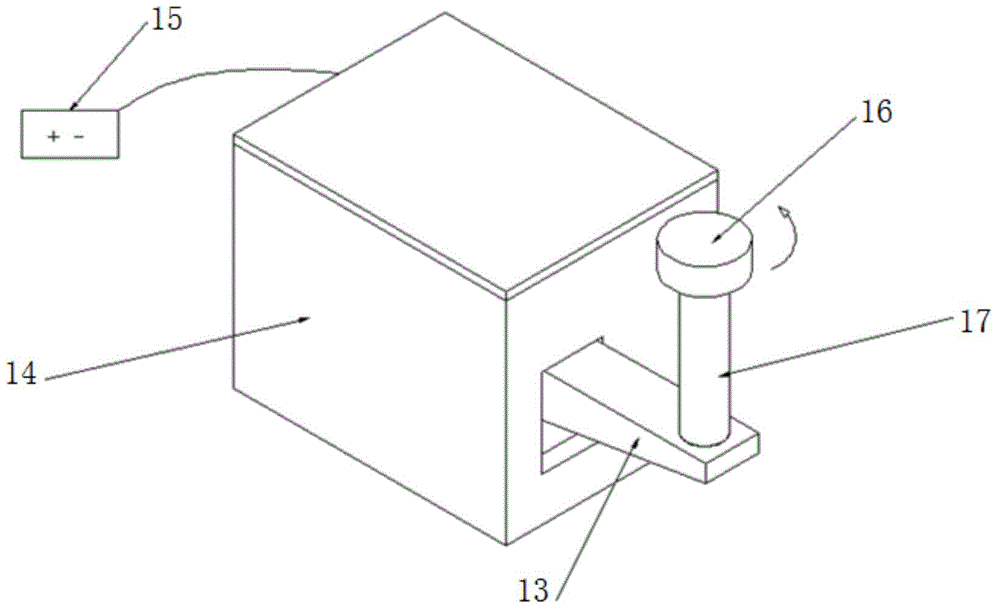
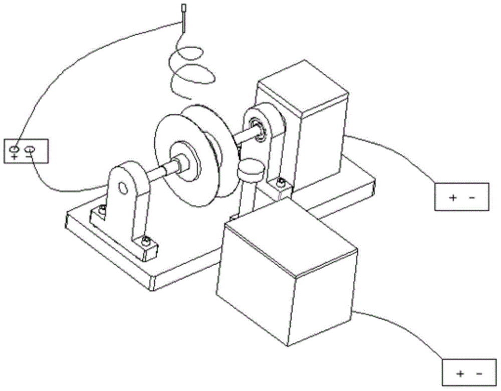
[0047] Biaxial PVA fiber scaffolds were electrospun using the above devices and methods. Wherein the PVA concentration is 10%, the set solution flow rate is 0.5ml / h, the voltage is 12KV, the distance between the needle point of the syringe and the parallel thin dish is 175mm, the thin dish rotating speed is 800r / min, and the distance between the parallel thin dish is 43mm, The circular collecting disk in the rotatable planar fiber collector moves at a speed of 5 mm / s, a rotation period of 10 min, a rotation angle of 90 degrees, a rotation speed of 10 mm / s, and an electrospinning environment temperature of 37. The electrospinning time was 2h. The obtained biaxially oriented fibers are as Figure 5 shown.


PUM


Abstract

The invention discloses an electrostatic spinning collection device and electrostatic spinning equipment with the device. The device comprises a directional fiber collector and a rotatable planar fiber receiver, wherein the directional fiber collector comprises a rotating shaft, two parallel disks mounted on the rotating shaft and a driving unit coupled with the rotating shaft; negative voltage is applied to the disks; fibers formed by splitting charged jet flow released from a positive voltage end are suspended between the two parallel disks in a directional manner; the rotatable planar fiber receiver comprises a receiving disk, and a rotation driving mechanism and a reciprocating driving mechanism which are coupled to the receiving disk; the reciprocating driving mechanism is used for supporting the receiving disk to get into or get out of a space between the two parallel disks; the rotary driving mechanism is used for rotating the receiving disk so as to adjust an angle of the fibers collected to the disk surface of the receiving disk. The invention also discloses an electrostatic spinning collection method using the electrostatic spinning collection device. The fibers electrically spun by the electrostatic spinning collection device are high in directing degree and are suitable for constructing highly ordered fiber tissue structures.

Description

technical field [0001] The invention relates to the field of electrospinning, in particular to an electrospinning collecting device, an electrospinning collecting method and an electrospinning device. Background technique [0002] Formhals published the world's first patent on electrospinning in 1934, and first proposed the concept of electrospinning. In the last ten years, with the rapid development of nanomaterials technology and interdisciplinary fields, electrospinning technology has received extensive attention from researchers. [0003] In traditional electrospinning, under the action of high voltage, the liquid droplets suspended on the needle tip of the syringe overcome their own surface tension to form a charged jet, and the flight trajectory of the jet in the electric field is a three-dimensional "jitter or vibration" of bending instability. Whip". After the solvent volatilizes or solidifies, it is collected on the fiber collector in the form of non-woven fabric....

Claims


Application Information

Patent Timeline
Patent Type & Authority Applications(China)
IPC IPC(8): D01D5/00
CPCD01D5/0076
Inventor 弥胜利刘长勇孔彬孙伟徐圆圆吴正洁刘多静苏鑫
Owner SHENZHEN GRADUATE SCHOOL TSINGHUA UNIV
Learn More