Centrifugal separation device for aircraft engine

An aero-engine and centrifugal separation technology, applied in the directions of engine components, engine lubrication, centrifuges, etc., can solve the problems of large oil consumption, unsuitable for aero-engine use, etc., to achieve high oil and gas separation efficiency, low processing and maintenance costs, The effect of improving the reuse rate of lubricating oil

Active Publication Date: 2016-08-24
CHINA AVIATION POWER MACHINE INST
View PDF6 Cites 1 Cited by
  • Summary
  • Abstract
  • Description
  • Claims
  • Application Information

AI Technical Summary

Problems solved by technology

[0005] The purpose of the present invention is to provide a centrifugal separation device for an aero-engine, to solve the technical problem that the medium-width blade-type centrifugal separation device in the prior art consumes a lot of lubricating oil and is not suitable for use in aero-engines

Method used


Image

  • Centrifugal separation device for aircraft engine
  • Centrifugal separation device for aircraft engine
  • Centrifugal separation device for aircraft engine

Examples


Embodiment 1

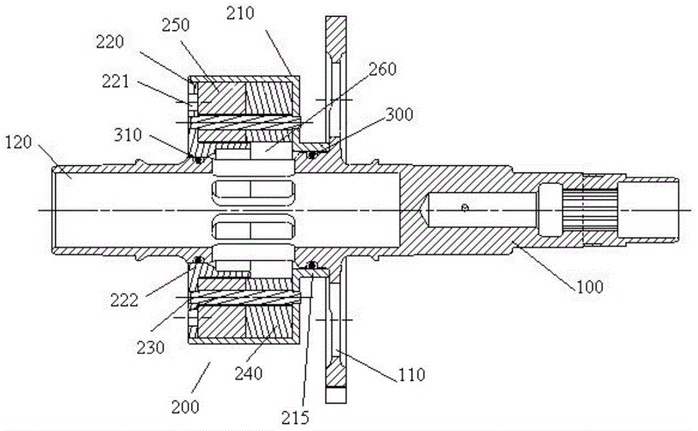
[0030] see figure 1 , the present invention provides a centrifugal separation device for an aero-engine, which includes a rotating shaft 100 and a centrifugal separator 200 sleeved on the outer wall of the rotating shaft 100 . The second end of the rotating shaft 100 is provided with a transmission gear 110 close to the housing. The rotating shaft 100 is rotated by the transmission gear 110 . The rotation of the rotating shaft 100 drives the centrifugal separator 200 to rotate, and a centrifugal force field is formed inside the centrifugal separator 200 .

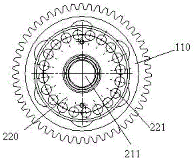
[0031] see figure 1 with figure 2 , the centrifugal separator 200 includes a first housing 210 , a second housing 220 , an oil-gas separation material and a pin 230 . One end of the first housing 210 is closed. One end of the first housing 210 is open. The inside of the first housing 210 forms a cavity. A first installation hole 211 is formed at the center of the first housing 210 along its axial direction. One end...

Embodiment 2

[0044] The difference from Embodiment 1 is that the housing is installed on the outer wall of the transmission gear 110 . It is fixed by three screws uniformly distributed along the circumference of the rotating shaft 100 . The housing is integrated with the rotating shaft 100 . The decrease in lubricating oil consumption relative to the web type centrifugal ventilator is the same as in Example 1.

Embodiment 3

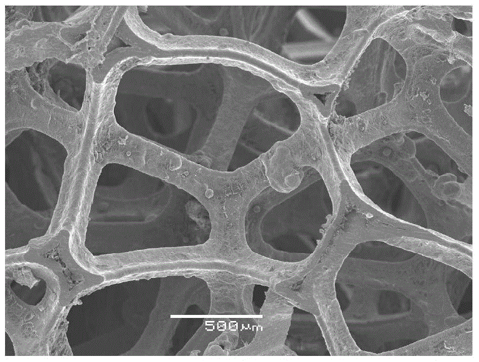
[0046] The difference from Embodiment 1 is that only one whole piece of porous metal is provided, and the thickness of the porous metal is 32.4mm. The hole metal used has an outer diameter of 87mm and an inner diameter of 47mm. The decrease in lubricating oil consumption relative to the web type centrifugal ventilator is the same as in Example 1.


PUM


Abstract

The invention provides a centrifugal separation device for an aero-engine. The centrifugal separation device comprises a rotating shaft and a centrifugal separator sleeving the outer wall of the rotating shaft, wherein the centrifugal separator comprises a shell sleeving the rotating shaft and multiporous metal; the multiporous metal fills the shell; a plurality of oil return holes are formed in one end face of the shell along the circumferential direction. Compared with an amplitude-plate blade type centrifugal separation device, the centrifugal separation device disclosed by the invention is simple and compact in structure, convenient to assemble and disassemble, light in weight, low in processing and maintenance cost and high in oil-gas separation efficiency.

Description

technical field [0001] The invention relates to the field of aero-engines, in particular to a centrifugal separation device for an aero-engine. Background technique [0002] The aero-engine lubricating oil system is an important part of the mechanical system of the aero-turboprop engine. It is responsible for supplying the lubricating oil required by each part of the aero-turboprop engine, and determines whether the engine can work safely and reliably. With the development of modern aero-engines toward high temperature, high speed, and high power-to-weight ratio, higher requirements are put forward for the design of aero-engine lubrication systems. [0003] The centrifugal separation device is an important part of the lubricating oil system. It is assembled in the accessory casing and mainly uses the centrifugal force field to separate the lubricating oil and hot gas in the transmission system. The separated lubricating oil is recycled and reused, so as to ensure that the t...

Claims


Application Information

Patent Timeline
Patent Type & Authority Patents(China)
IPC IPC(8): F02C7/06B04B5/00B04B7/00
Inventor 曹鹏郭晖郑鹏薛筱萌
Owner CHINA AVIATION POWER MACHINE INST
Why Eureka
Try Eureka