Wheel diameter difference member speed reducer

A differential reducer and reducer technology, applied in transmission parts, gear transmissions, belts/chains/gears, etc., can solve the problems of high process requirements, no impact resistance, limited friction transmission speed, etc. Tooth surface technology and surface heat treatment technology, strong impact resistance, and the effect of improved processing technology

Inactive Publication Date: 2014-08-13
张小龙 +1
View PDF6 Cites 10 Cited by
  • Summary
  • Abstract
  • Description
  • Claims
  • Application Information

AI Technical Summary

Problems solved by technology

The planetary gear reducer has a small reduction ratio range, the worm gear reducer is a surface contact friction transmission, the friction transmission speed is limited (not exceeding 1500r / min), and the reduction ratio range is not large; the cycloidal gear reducer is a surface contact multi-teeth meshing without friction Transmission, high transmission precision, durable, but its crankshaft structure is an unbalanced movement that is prone to vibration, and the output is a pinhole clearance fit connection that is not compact and impact-resistant; the RV type cycloidal gear reducer is a multi-swing disc and multi-crankshaft type. Balanced motion, compact structure, strong impact resistance, but its complex structure, large volume, high process requirements, and small range of reduction ratio; The output is an elastic piece cup-shaped ring, and the distance between the teeth meshing position and the output part must be elastically variable, and its structure has poor impact resistance; at present, the development of various industries is constantly introducing new ones, and the requirements for reducers are also increasing

Method used


Image

  • Wheel diameter difference member speed reducer
  • Wheel diameter difference member speed reducer

Examples


Embodiment

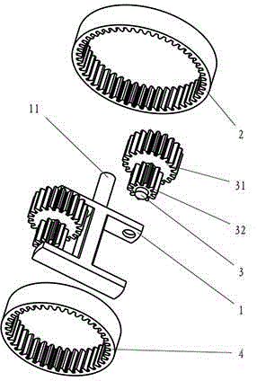
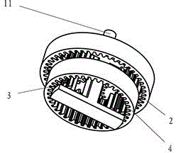
[0019] see figure 1 and figure 2 , the present invention discloses a radial differential sub-reducer, including a radial differential sub-frame 1, a fixed mother shell wheel 2, a radial differential sub-3, and a differential shell wheel 4, wherein: the radial differential sub-frame 3 includes a differential sub-main wheel 31 and Difference sub-wheel 32, diameter difference sub-frame axle 11.

[0020] Implementation details: the working principle of the radial differential sub-reducer, the differential sub-frame is set as the input speed shaft, the differential sub-frame and the radial differential sub-frame are linked, the differential sub-gear wheel of the radial differential sub-gear is meshed with the fixed mother shell wheel, and the fixed mother shell wheel It exists in a fixed and non-rotating form, and can obtain the linear velocity of the input speed reflected on the differential sub-master wheel. The angular velocity corresponding to the speed is the same as the ro...


PUM


Abstract

The invention discloses a wheel diameter difference member speed reducer. The wheel diameter difference member speed reducer comprises a wheel diameter difference member frame, a fixing main casing wheel, wheel diameter difference members and a differential motion casing wheel; the wheel diameter difference members are fixed inside the wheel diameter difference member frame in a rotary mode; the wheel diameter difference members are in transmission enragement with the fixing main casing wheel and the differential motion casing wheel; the wheel diameter difference member frame and the differential motion casing wheel can be input and output shafts; the wheel diameter difference member frame, the fixing main casing wheel and the differential motion casing wheel are arranged coaxially. The wheel diameter difference member speed reducer difference member speed reducer has the advantages of being simple in structure, low in machining difficulty, large in output power, strong in shock resistant capability and large in speed reducing range.

Description

[0001] The invention relates to a reducer, in particular to a radial differential reducer. Background technique [0002] The existing reducers mainly include: planetary reducer, worm gear reducer, cycloid reducer and harmonic reducer. The planetary gear reducer has a small reduction ratio range, the worm gear reducer is a surface contact friction transmission, the friction transmission speed is limited (not exceeding 1500r / min), and the reduction ratio range is not large; the cycloidal gear reducer is a surface contact multi-teeth meshing without friction Transmission, high transmission precision, durable, but its crankshaft structure is an unbalanced movement that is prone to vibration, and the output is a pinhole clearance fit connection that is not compact and impact-resistant; the RV type cycloidal gear reducer is a multi-swing disc and multi-crankshaft type. Balanced motion, compact structure, strong impact resistance, but its complex structure, large volume, high process...

Claims


Application Information

Patent Timeline
Patent Type & Authority Applications(China)
IPC IPC(8): F16H3/04F16H57/023
CPCF16H1/32F16H57/023
Inventor 张小龙张东奇
Owner 张小龙
Why Eureka
Try Eureka