Rotary joint for connecting pipeline system

A technology of rotary joint and pipeline system, applied in the direction of pipe/pipe joint/pipe fitting, adjustable connection, pipe element, etc., can solve the problems of unsuitable vertical installation of axis, high machining precision of semi-circle raceway, unable to rotate normally, etc. Achieve the effect of low cost, good processing technology and improved operating efficiency

Active Publication Date: 2014-08-13
天津市长龙宏业燃气设备有限公司
View PDF5 Cites 5 Cited by
  • Summary
  • Abstract
  • Description
  • Claims
  • Application Information

AI Technical Summary

Problems solved by technology

[0005] The above-mentioned rotary joints of the prior art have the following defects: the above-mentioned rotary joints of the prior art are suitable for horizontal installation of the axis, but not suitable for vertical installation of the axis
Because the weight of the relatively rotating shaft and sleeve acts on the semicircular raceway 26, the ball 24 will cause wear to the semicircular raceway 26 after running for a period of time, and the axial relative position between the joint outer sleeve 23 and the joint inner sleeve 25 will move, causing the raceway Misalignment, the rotation cannot be rotated normally, so that it cannot be used; in addition, the semicircular raceway has high machining accuracy, poor workmanship, and difficult processing

Method used


Image

  • Rotary joint for connecting pipeline system
  • Rotary joint for connecting pipeline system
  • Rotary joint for connecting pipeline system

Examples


Embodiment Construction

[0023] Embodiments of the present invention will be further described below in conjunction with the accompanying drawings.

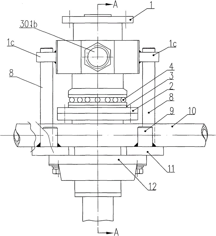
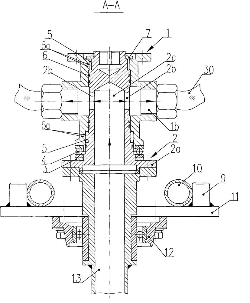
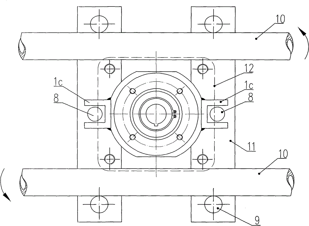
[0024] Such as Figure 1 to Figure 3 As shown, the present invention provides a rotary joint connected to a pipeline system. The rotary joint includes: a casing 1 vertically arranged in the axial direction, and the casing 1 has a casing through hole 1b connected to the output pipe 30, and the casing 1 is connected to a drive It turns the rotary drive mechanism.

[0025] The present invention comprises: a central shaft 2, the outer diameter of the upper end of the central shaft 2 is hingedly inserted into the inner diameter hole of the jacket 1, the lower end of the central shaft 2 has a blind hole 2c on the side wall of the blind hole 2c, and there is a central shaft through hole 2b on the side wall of the central shaft. The shaft through hole 2b communicates with the jacket through hole 1b and the blind hole 2c; a pressure bearing 4 is arranged between...


PUM


Abstract

The invention discloses a rotary joint for connecting a pipeline system. The rotary joint comprises an outer sleeve, wherein the outer sleeve is axially and vertically arranged, the outer sleeve is provided with an outer sleeve through hole, and the outer sleeve is connected with a rotary driving mechanism; the upper end of a center shaft is inserted in an outer sleeve inner hole in a sealing and hinging way, the lower end of the center shaft is provided with a blind hole, the side wall of the blind hole is provided with a center shaft through hole, and the center shaft through hole is communicated with the outer sleeve through hole and the blind hole; pressure bearings are arranged between an end surface flange at the lower end of the center shaft and the end surface of the outer sleeve. The rotary joint disclosed by the invention has the beneficial effects that the defect of the prior art is overcome, the axis of the rotary joint is vertically arranged, the weight of the outer sleeve and a connecting piece is borne by the pressure bearings, a raceway does not deform, the abrasion during a working process is reduced, the outer sleeve and the center shaft are enabled to be in a good stress state and a long-term hinging state, the service life of the rotary joint is prolonged, the normal work of the rotary joint is ensured, the running efficiency is increased, the raceway is annular, the processing technology is good, and the cost is low.

Description

technical field [0001] The invention relates to a joint connected with a pipeline system, in particular to a rotary joint connected with the pipeline system. Background technique [0002] In the prior art, the rotary joint connected with the piping system is usually installed in the piping system in which a fixed piping is connected on one side and a rotating piping is connected on the other side. [0003] Figure 4 is a sectional view of a prior art rotary joint. [0004] Such as Figure 4 As shown, the rotary joint in the prior art includes: a joint outer sleeve 23, a joint inner sleeve 25 and a ball 24. One end of the joint outer sleeve 23 is assembled with one end of the joint inner sleeve 25 to form a sealing surface, and the joint outer sleeve 23 and the joint inner sleeve 25 are sealed. There is a semicircular raceway 26 sunken to its inner side on the surface, and a plurality of balls 24 are filled in the semicircular raceway 26; the other end of the joint outer sle...

Claims


Application Information

Patent Timeline
Patent Type & Authority Applications(China)
IPC IPC(8): F16L27/08
CPCF16L39/06
Inventor 王建国
Owner 天津市长龙宏业燃气设备有限公司
Why Eureka
Try Eureka