
Device and method for rapidly detecting optical grating auxiliary gap at high precision

A grating pair, high-precision technology, used in measuring devices, electrical devices, instruments, etc., can solve the problems of low measurement accuracy, large structure size, low efficiency, etc., and achieve distance measurement, high-precision detection, and simple structure. Effect

Inactive Publication Date: 2014-08-13
CHANGCHUN INST OF OPTICS FINE MECHANICS & PHYSICS CHINESE ACAD OF SCI
View PDF7 Cites 6 Cited by
  • Summary
  • Abstract
  • Description
  • Claims
  • Application Information

AI Technical Summary

Problems solved by technology

[0006] In order to solve the problems of low measurement accuracy, low efficiency, and large structural size of the existing non-contact optical method for detecting the sub-gap of the grating, the present invention provides a device and method for quickly detecting the sub-gap of the grating with high precision

Method used


Image

  • Device and method for rapidly detecting optical grating auxiliary gap at high precision
  • Device and method for rapidly detecting optical grating auxiliary gap at high precision
  • Device and method for rapidly detecting optical grating auxiliary gap at high precision

Examples


Embodiment Construction

[0018] The present invention will be described in further detail below in conjunction with the accompanying drawings.

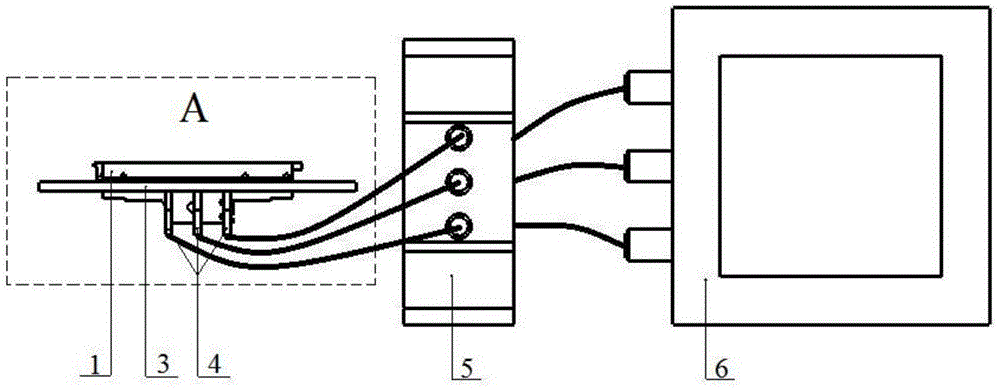
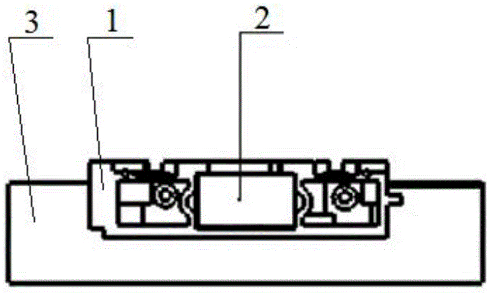
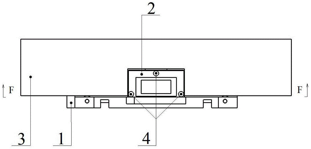
[0019] like figure 1 As shown, the device for high-precision and rapid detection of grating sub-gap of the present invention includes a carriage 1, an indicating grating 2, a main grating 3, three eddy current sensors 4, a grating displacement measurement system 5 and a digital display 6. like figure 2 As shown, the indicating grating 2 is glued and fixed on the carriage 1, and then the carriage 1 is placed on the main grating 3, and the plane where the indicating grating 2 is located and the plane where the main grating 3 is located are parallel to each other. like image 3 As shown, three eddy current sensors 4 are installed below the indicating grating 2, distributed in an isosceles triangle with the largest area, as shown in Figure 4 As shown, the three probes of the three eddy current sensors 4 are on the same plane, and this plane can be flush with...


PUM


Abstract

The invention relates to a device and method for rapidly detecting an optical grating auxiliary gap at high precision and relates to the field of photoelectric measurement. The problems that an existing non-contact optical method for detecting the optical grating auxiliary gap is low in measurement precision and efficiency, and a structure is large in size are solved. The device comprises a main grating, a carriage, an indicating grating, three electrical vortex sensors, a grating displacement measuring system and a digital display screen, wherein the three electrical vortex sensors are installed below the indicating grating, the grating displacement measuring system is connected with the output ends of the three electrical vortex sensors, and the digital display screen is connected with the output end of the grating displacement measuring system. The three electrical vortex sensors are distributed in the shape of an isosceles triangle with the largest area, three probes of the sensors are located on the same plane, and the plane is flush with the upper surface of the main grating or spaced by a certain distance which is the initial zero position; the periphery of the indicating grating is plated with chromium metal layers equal in width and thickness, the thickness is larger than 0.65 micrometers, and the width of the chromium metal layers is larger than the diameter of the probes. The measurement precision can reach the micrometer level, measurement is rapidly and accurately performed in real time, the structure is simple and small, and distance measuring for glass is achieved.

Description

technical field [0001] The invention relates to the technical field of photoelectric measurement, in particular to a device and method for quickly detecting the sub-gap of a grating with high precision. Background technique [0002] In the field of precision measurement and displacement control, grating rulers are mostly used as measurement methods. Grating rulers are recognized as the most economical and practical technical equipment in high-precision measurement, and are widely used in engineering technology fields involving measurement, such as machine tools and displacement consoles. [0003] The core component of the grating scale is a pair of grating pairs, namely the main grating 3 and the indicator grating 2. A certain gap needs to be maintained between the two to work normally. During the bonding process of the indicator grating 2 and the carriage 1, the structure ensures that the grating pair After bonding, judge whether it meets the requirements by means of detect...

Claims


Application Information

Patent Timeline
Patent Type & Authority Applications(China)
IPC IPC(8): G01B7/14
Inventor 张雪鹏孙强吴宏圣
Owner CHANGCHUN INST OF OPTICS FINE MECHANICS & PHYSICS CHINESE ACAD OF SCI
Learn More