Tool wear state detection method for industrial unbalanced data

A tool wear and balance data technology, applied in the field of CNC machine tool state detection, can solve the problems of insufficient high-quality sensor data and uneven distribution, so as to improve the real-time detection effect, ensure the distribution consistency, and realize the effect of high-precision detection

Active Publication Date: 2020-09-08
ZHEJIANG UNIV
View PDF8 Cites 9 Cited by
  • Summary
  • Abstract
  • Description
  • Claims
  • Application Information

AI Technical Summary

Problems solved by technology
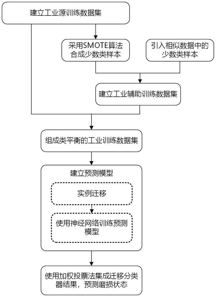
Such a method does not take into account the serious shortage and uneven distribution of high-quality sensor data in actual industrial production, and the classification results obtained tend to tend to the majority class.
Therefore, the present invention proposes a tool wear state detection method for industrial unbalanced data, which can effectively solve the problem of high-precision detection of tool wear state under the condition of less and unbalanced industrial data

Method used


Image

  • Tool wear state detection method for industrial unbalanced data
  • Tool wear state detection method for industrial unbalanced data
  • Tool wear state detection method for industrial unbalanced data

Examples


specific Embodiment

[0060] This example uses the game data of the 2010 PHM (Fault Diagnosis and Health Management) Association Data Contest to verify the method for detecting the wear state of the CNC machine tools proposed by the present invention.

[0061] The processing parameters of the CNC machine tools are: the spindle speed is 10400rpm, the feed rate in the x-axis direction is 1555mm / min, the radial cutting depth is 0.125mm, and the axial cutting depth is 0.2mm. The sampling frequency of the measurement system is 50kHz. Each machining process consists of 315 milling operations. After each milling operation, the tool is stopped and the wear of the tool is measured using a LEICA MZ12 microscope. The data used in this example includes the data of 6 processing processes, and 6 sets of sensor measurement data are obtained, namely C1, C2, C3, C4, C5, and C6.

[0062] The experimental task of this example is to use the preprocessed tool sensor measurement data and the corresponding tool wear sta...

specific Embodiment approach

[0065] S1. Setting of training data and test data:

[0066] In order to meet the basic requirements of the tool wear state detection method proposed in the present invention, the competition data is divided into a test data set, a source training data set and an auxiliary training data set. The distribution of the source training data set and the test data set must be consistent, and the distribution of the auxiliary training data set and the test data set is similar but not consistent.

[0067] Based on this requirement, in the competition data, three data sets C1, C4, and C6 were selected as training and testing data for verifying the method proposed by the present invention. The specific method is as follows: randomly select one-third of the data in a data set as the test set; use the remaining two-thirds of the data in the data set as the source training set; use the minority class samples in the remaining two data sets as the auxiliary training set . In this way, since ...


PUM


Abstract

The invention discloses a tool wear state detection method for industrial unbalanced data. The method comprises the steps of: preprocessing the historical monitoring data of the numerically-controlledmachine tool cutter obtained by the sensor to form source training data with the cutter wear state label; carrying out the same preprocessing of the historical monitoring data of the to-be-detected tool, and forming auxiliary training data together with a few types of data obtained through the oversampling synthesis of the source training data; training a cutter wear state prediction model by using the training data through a transfer learning method; and preprocessing and inputting the real-time sensor data of the to-be-detected cutter into the prediction model, and obtaining the abrasion state of the cutter in real time. According to the method, the balance of the training data is fully ensured, and the distribution consistency of the training data and the test data is fully ensured, sothat the problem of high-precision detection of the tool wear state under the condition of less and unbalanced industrial data volume is solved.

Description

technical field [0001] The invention relates to a workpiece wear detection method belonging to the state detection field of numerical control machine tools, in particular to a tool wear state detection method for industrial unbalanced data, and relates to the field of deep learning and transfer learning unbalanced classification in machine learning . Background technique [0002] In modern machining and production operations, the wear of CNC machine tools is a very common phenomenon. The wear of the tool directly affects the dimensional accuracy, roughness, and quality of the processed part, and may even lead to the scrapping of the processed part, which increases production costs and reduces processing efficiency. However, if the wear status of CNC machine tools can be monitored in real time, and the tools in the fault state can be replaced and maintained in a timely manner, the quality of processed products can be effectively improved, production efficiency can be improve...

Claims


Application Information

Patent Timeline
Patent Type & Authority Applications(China)
IPC IPC(8): G06F30/27G06N3/04G06N3/08G05B19/4065
CPCG06F30/27G06N3/08G05B19/4065G05B2219/45136G06N3/048G06N3/045
Inventor 刘振宇刘惠张朔郏维强谭建荣
Owner ZHEJIANG UNIV
Why Eureka
Try Eureka