
Method for deviation adjustment for detection of spatial position of steel belt roll system

A technology of spatial position and roll system, which is applied to the detection and adjustment of the spatial position of the steel belt roll system, and the field of position detection and deviation adjustment, which can solve the poor effect of the spatial position adjustment of the rolling system, the adjustment process is time-consuming and laborious, and the adjustment accuracy is low and other problems, to achieve the effect of high degree of detection automation, convenient detection and high precision

Inactive Publication Date: 2014-08-13
上海宝冶工程技术有限公司
View PDF3 Cites 11 Cited by
  • Summary
  • Abstract
  • Description
  • Claims
  • Application Information

AI Technical Summary

Problems solved by technology

[0004] The technical problem to be solved in the present invention is: the existing adjustment of the levelness and verticality of the rolling system of the steel belt mainly adopts the traditional way of artificially using detection tools such as level rulers and gratings for detection, and the detection accuracy is low. The accuracy is low, the effect of adjusting the spatial position of the rolling system is not good, and the adjustment process is time-consuming and laborious

Method used


Image

  • Method for deviation adjustment for detection of spatial position of steel belt roll system
  • Method for deviation adjustment for detection of spatial position of steel belt roll system
  • Method for deviation adjustment for detection of spatial position of steel belt roll system

Examples


Embodiment Construction

[0026] The present invention will be further described below in conjunction with the accompanying drawings and specific embodiments.

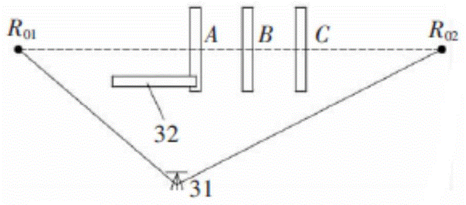
[0027] like figure 1 As shown, R 01 , R 02 The two datum center points for the roller shaft inspection, and the line connecting the two points is used as the datum reference line for the roller system inspection. Our purpose is to use the total station to measure the spatial positional relationship between the roller shafts A, B, C and the datum reference line—— Verticality / levelness, etc., and then adjust the position of its roller system.

[0028] The specific detection includes the following steps:

[0029] see figure 1 , set up the total station between two center points; total station 31, two reference points R 01 , R 02 Three points form a triangle;

[0030] see figure 1 , fix a tooling swing arm, that is, the bearing rod 31, on the measured stick axis A;

[0031] Detection of R by Total Station 01 , R 02 Coordinates, the coord...


PUM


Abstract

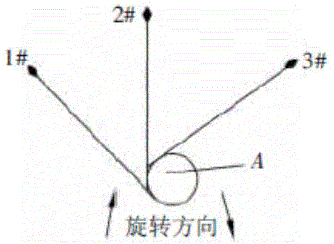
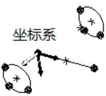
The invention relates to a method for deviation adjustment for detection of the spatial position of a steel belt roll system. A datum point R01 and a datum point R02 located on the portions, on the two sides of the roll system, of a device bearing the steel belt roll system and on the center axis of the roll system are selected; a total station is erected between the two datum points; the position of the total station is set to serve as an origin of space coordinates, the connecting line of the two datum points serves as the X direction, the Z direction is vertically upwards, and the coordinates of the datum point R01 and the datum point R02 are detected through the total station; a detected roll shaft is rotated, the space coordinates of at least three different rotation positions on one vertical section of the detected roll shaft are detected through the total station; the coordinates of the center of a circle where each point is located are obtained by a computer system, and therefore the space coordinates of each point on the central axis of a steel roll are obtained; the space coordinates of the points on the central axis of the detected steel roll are compared with the space coordinates of the points on the central axis at the steel roll standard position obtained in advance and the deviation directions and the deviation distances of the points on the central axis are obtained; according to the deviation directions and the deviation distances, space position adjustment is conducted on the detected steel roll.

Description

technical field [0001] The invention relates to a position detection and deviation adjustment method, in particular to a detection and deviation adjustment method for the spatial position of a steel belt roll system, belonging to the technical field of detection and deviation adjustment. Background technique [0002] Due to the uneven settlement of the equipment foundation for the coiling and conveying of the steel strip, the spatial position of the equipment deviates, causing strip deviation and wrinkling, seriously affecting product quality, and even causing downtime. [0003] In the prior art, for the adjustment of the levelness and verticality of the rolling system of the steel belt, the traditional detection method is mainly adopted by using detection tools such as a spirit level and a grating. The detection accuracy is low, and the adjustment accuracy is low. The effect of spatial position adjustment is not good, and the adjustment process is time-consuming and laborio...

Claims


Application Information

Patent Timeline
IPC IPC(8): G01B11/00
Inventor 付永宝刘晓阳刚张立华李国辉薛奡
Owner 上海宝冶工程技术有限公司
Learn More