Mutual-shooting imaging system for deep-space exploration lander and deep-space exploration rover

An imaging system and deep space exploration technology, applied in the direction of camera devices, etc., can solve the problems of low reliability, low image resolution, low camera image resolution, etc., and achieve the effects of improving reliability, improving resolution, and reducing risks.

Active Publication Date: 2015-06-10
BEIJING INST OF SPACECRAFT SYST ENG
View PDF1 Cites 0 Cited by
  • Summary
  • Abstract
  • Description
  • Claims
  • Application Information

AI Technical Summary

Problems solved by technology

However, the realization of the zoom camera will have a certain impact on temperature control, weight, power consumption, installation size, dustproof, control, etc., which will bring great difficulties and low reliability to deep space exploration projects
At present, there is no zoom camera in the field of deep space exploration at home and abroad
[0006] Second, it is necessary to follow the movement status of the patrol device on the lunar surface
At present, the best imaging system to achieve this requirement is to use a camera, which has a high frame rate and a coherent video image. However, due to the limitation of the deep space digital transmission code rate and the demand for real-time downloading, the detector pixel of the camera must be required. A small number or a high image compression ratio, resulting in a lower resolution of the camera image
[0007] In order to overcome the low reliability of the zoom camera in deep space exploration and the low resolution of the camera image, a two-device mutual imaging imaging system for deep space exploration is proposed to meet the task requirements of the two-device inter-shooting

Method used


Image

  • Mutual-shooting imaging system for deep-space exploration lander and deep-space exploration rover
  • Mutual-shooting imaging system for deep-space exploration lander and deep-space exploration rover
  • Mutual-shooting imaging system for deep-space exploration lander and deep-space exploration rover

Examples


Embodiment Construction

[0024] The present invention will be described in detail below in conjunction with the accompanying drawings and specific embodiments.

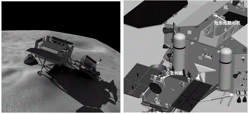
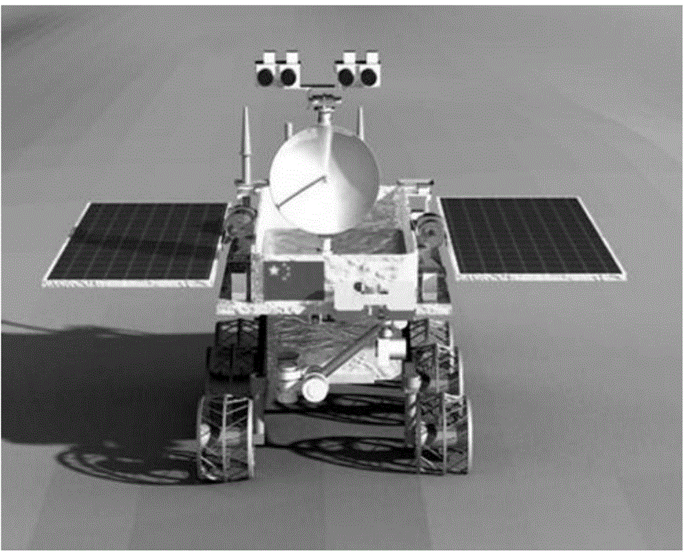
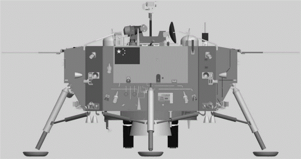
[0025] The present invention is a two-device imaging system for deep space exploration. The system is composed of a topography camera, a camera pointing mechanism platform, a panoramic camera and a mast platform; wherein the camera pointing mechanism platform is installed on the top plate of the lander. The terrain camera is installed on the camera pointing mechanism cloud platform; the mast platform is installed on the top plate of the patrol device, and the panoramic camera is installed on the mast platform; Together, the two devices can take pictures together, and the patrol device can follow up the movement of the lunar surface.

[0026] The functions, observation tasks and installation positions of the two-device mutual imaging system are shown in Table 1, and the installation layout is as follows figure 1 shown.

[0027] Table 1 Funct...


PUM


Abstract

The invention provides a mutual-shooting imaging system for a deep-space exploration lander and a deep-space exploration rover. The system consists of a landform physiognomy camera, a cameral pointing mechanism holder, a panorama camera and a mast holder; the landform physiognomy camera is installed on the camera pointing mechanism holder, and the panorama camera is installed on the mast holder; the cameral pointing mechanism holder is installed on the lander, the yaw angle scope is -175 DEG to +175 DEG, and the pitch angle copse is -60 DEG to +60 DEG; and the mast holder is installed on the rover, the yaw angle scope is -178.5 DEG to +178.5 DEG, and the pitch angle copse is -60 DEG to +90 DEG. According to the system, the lander and the rover are both provided with a camera for cooperative working with a corresponding mechanism moving part, the two cameras respectively perform static shooting on the lander and the rover, and also perform following shooting on movement state of the rover on moon surface, so that the quantity of cameras configured to an imaging system.

Description

technical field [0001] The invention belongs to the technical field of aerospace optical payloads, and in particular relates to a mutual imaging system for two deep space exploration devices (a lander and a patrol device, hereinafter referred to as the two devices). Background technique [0002] Cameras are the eyes of satellites or probes, and are the main payload that almost all satellites or probes carry. The United States, Europe, Japan and other countries are carrying out multiple cameras on their landers or lunar rovers during their deep space exploration activities, undertaking tasks such as photography, monitoring, and auxiliary navigation, or by configuring various types of cameras. Realize more functions. [0003] At present, among the engineering tasks of foreign deep space probes including lander and patrol device, there is no mutual shooting task between the two devices. [0004] The demand for the imaging system of my country's deep space exploration two-devi...

Claims


Application Information

Patent Timeline
Patent Type & Authority Patents(China)
IPC IPC(8): G01C11/02
CPCG01C11/02
Inventor 邹昕陈丽平邓湘金张熇吴学英顾征
Owner BEIJING INST OF SPACECRAFT SYST ENG
Why Eureka
Try Eureka