

Double-beam splitting system
A spectroscopic system and double-beam technology, applied in spectrometry/spectrophotometry/monochromator, optical radiation measurement, using diffraction elements to generate spectra, etc., can solve problems such as high cost, measurement errors, and large volume. Achieve volume reduction, avoid measurement errors, and facilitate miniaturization
- Summary
- Abstract
- Description
- Claims
- Application Information
AI Technical Summary
Problems solved by technology
Method used
Image

Examples
Embodiment 1
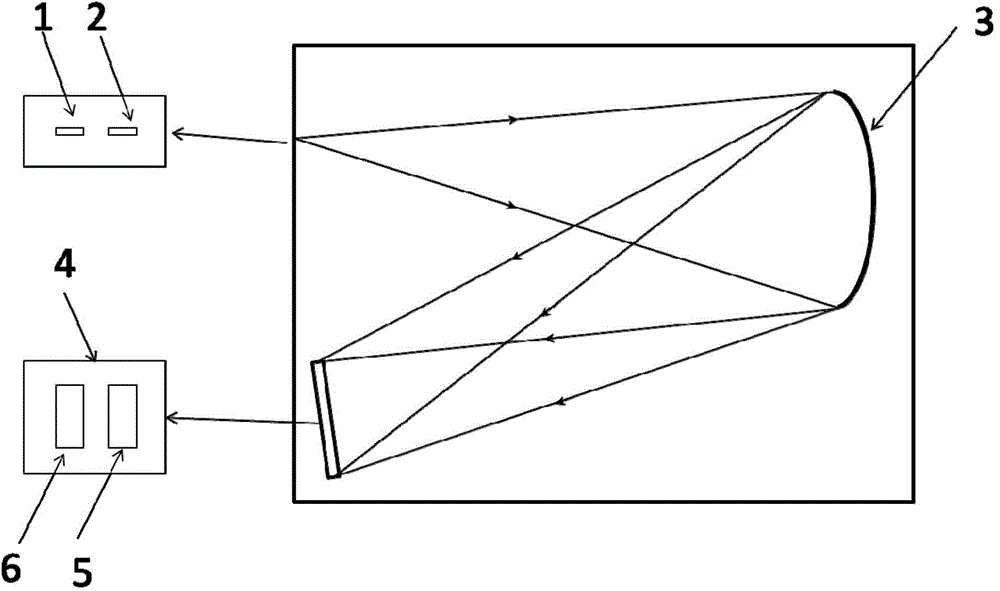
[0019] Embodiment one: see attached figure 1 , the double-beam splitting system of the present invention includes an incident slit I1, an incident slit II2, a diffraction grating and a detector, the incident slit I1 and the incident slit II2 are arranged side by side in the length direction, that is, perpendicular to the dispersion direction, respectively The sample light and reference light input by the incident slit I1 and the incident slit II2 are respectively dispersed by the diffraction grating, and the sample beam spectrum 5 and the reference beam spectrum 6 after being dispersed by the diffraction grating are arranged side by side on the detector without interfering with each other, so that A beam splitting system realizes the function of a double beam splitting system.
[0020] The diffraction grating is a concave grating 3 , and the detector is an area array detector 4 .
[0021] The distance between the sample beam spectrum 5 and the reference beam spectrum 6 is rel...
Embodiment 2
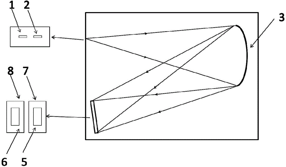
[0023] See attached figure 2 The difference between this embodiment and Embodiment 1 is that the diffraction grating is a concave grating 3, and the detector includes a linear array detector I7 and a linear array detector II8, and the linear array detector I7 and the linear array detector II8 are arranged side by side The sample beam spectrum 5 and the reference beam spectrum 6 are arranged on the line array detector I7 and the line array detector II8 respectively.
[0024] The sample light and reference light incident from the incident slit I1 and the incident slit II2 are dispersed by the concave grating 3, and the sample beam spectrum 5 and the reference beam spectrum 6 are respectively received by the linear array detector I7 and the linear array detector II8. The beam spectrum 5 and the reference beam spectrum 6 are arranged side by side without interfering with each other, so that one beam splitting system can realize the function of a double beam splitting system.
[...
Embodiment 3
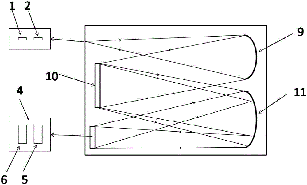
[0027] See attached image 3 The difference between this embodiment and Embodiment 1 is that the diffraction grating is a plane grating 10, the detector is an area array detector 4, and the spectroscopic system also includes a collimating mirror 9 and an imaging mirror 11; The sample light and reference light incident on the slit I1 and the incident slit II2 pass through the collimating mirror 9 and then incident on the plane grating 10 as parallel light. After being dispersed by the plane grating 10 and converged by the imaging mirror 11, the sample beam spectrum 5 and the reference light The beam spectra 6 are respectively arranged side by side on the area array detector 4 without interfering with each other, so that one beam splitting system can realize the function of a double beam splitting system.
PUM
 Abstract
Description
Claims
Application Information