Fault diagnosis method and device for nuclear detector

A technology of fault diagnosis device and nuclear detector, which is applied to measurement devices, instruments, measuring electricity and other directions, can solve the problem that it is difficult to find and repair instrument faults in a timely and effective manner, the health of inspectors is strongly radiated, and nuclear detectors are prone to failure. And other issues

Active Publication Date: 2014-08-13
NANHUA UNIV
View PDF6 Cites 6 Cited by
  • Summary
  • Abstract
  • Description
  • Claims
  • Application Information

AI Technical Summary

Problems solved by technology

The signal-to-noise ratio of the output signal of the nuclear detector is low, the background clutter is strong, and it often works in the harsh environment of high temperature and high radiation, which makes the nuclear detector prone to failure
[0003] At present, in order to ensure the reliability, maintainability and safety of the control and monitoring system, nuclear detectors are usually inspected manually. Although some obvious physical damage can be found in the nuclear detectors through manual inspection, they cannot detect the internal damage of the nuclear detector. Moreover, the installation sites of most nuclear detectors have relatively high radiation, and it is difficult to find and repair these instrument failures by humans in a timely and effective manner, and the health of inspection personnel will also be affected by the strong radiation and toxic and harmful gases at the production site. the harm of
Correctly judging the nature, severity and location of nuclear detector failures often requires operators to have rich experience and a deep understanding of the control and monitoring system, otherwise there may be missed judgments, misjudgments, and misoperations

Method used


Image

  • Fault diagnosis method and device for nuclear detector

Examples


Embodiment Construction

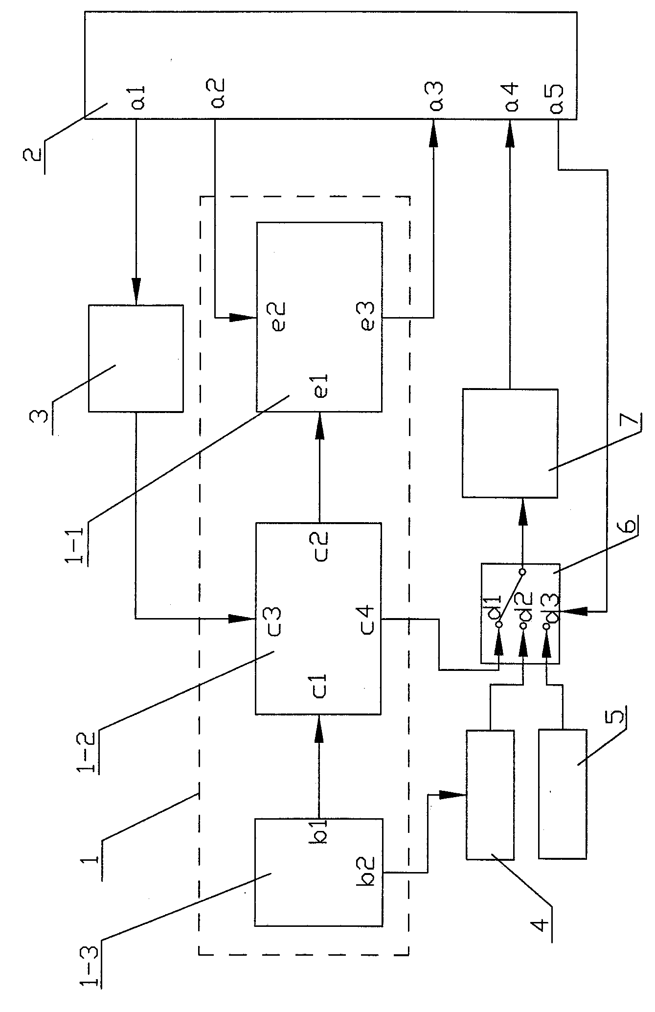
[0034] A method for fault diagnosis of a nuclear detector, the signal output end of the D / A converter 3 in the fault diagnosis device is connected to the second signal input end c3 of the analog amplifier circuit 1-2 in the nuclear detector 1, and the analog amplification The second signal output end c4 of the circuit 1-2 is connected with the d1 end of the multi-choice switch 6 in the fault diagnosis device, and the second signal output end a2 of the CPU processor 2 in the fault diagnosis device is connected with the shaper in the nuclear detector 1 The second signal input end e2 of the circuit 1-1 is connected, the signal output end e3 of the shaping circuit 1-1 is connected with the third signal input end a3 of the CPU processor 2, and the first signal input end a3 of the nuclear probe 1-3 in the nuclear detector 1 The second signal output terminal b2 is connected to the signal input terminal of the high and low voltage detection module 4 in the fault diagnosis device.

[0...


PUM


Abstract

The invention discloses a fault diagnosis method and device for a nuclear detector. The fault diagnosis device is connected with the nuclear detector, under the normal working condition, signal data of a digital forming circuit, a simulation amplification circuit and a nuclear probe of the nuclear detector are collected through the fault diagnosis device, characteristic information of the nuclear detector can be extracted in a data processing manner, and a data information base in a normal state can be established by extracting the characteristic values of the data. When faults occur or are about to occur, one or more of characteristic parameter information can be changed, so as to be different from parameter information under the normal working condition. When the nuclear detector is used for monitoring or detecting, the characteristic parameter can be obtained through acquiring the obtained data and by adopting a data analysis method, whether the nuclear detector has an abnormal fault is judged by difference through comparing the characteristic parameter and the information of the data information base, and the type and the position of the faults can be judged, so that the intelligent judgment on the faults of the nuclear detector can be realized.

Description

technical field [0001] The invention belongs to the field of automatic control, in particular to a fault diagnosis method and device for nuclear radiation detectors. Background technique [0002] As an important nuclear radiation measuring instrument in nuclear science research, nuclear radiation detector is the source of obtaining various radiation information. The signal-to-noise ratio of the output signal of the nuclear detector is low, the background clutter is strong, and it often works in the harsh environment of high temperature and high radiation, which makes the nuclear detector prone to failure. [0003] At present, in order to ensure the reliability, maintainability and safety of the control and monitoring system, nuclear detectors are usually inspected manually. Although some obvious physical damage can be found in the nuclear detectors through manual inspections, they cannot detect the inherent damage of the nuclear detectors. Moreover, the installation sites o...

Claims


Application Information

Patent Timeline
IPC IPC(8): G01R31/00
Inventor 颜拥军周剑良王庆震付德顺曹真伟祁铁涛易凌凡
Owner NANHUA UNIV
Why Eureka
Try Eureka