Method for determining ampere-turn change percentage range of coil according to dynamic magnetic field associated with coupled oscillation in Hall thruster

A Hall thruster and dynamic magnetic field technology, applied in the field of aerospace, can solve the problem of inaccurate range of coil ampere-turn change percentage, and achieve the effect of overcoming limitations

Inactive Publication Date: 2014-08-13
HARBIN INST OF TECH
View PDF4 Cites 8 Cited by
  • Summary
  • Abstract
  • Description
  • Claims
  • Application Information

AI Technical Summary

Problems solved by technology

[0004] The purpose of the present invention is to solve the problem of inaccurate determination of the percentage range of the ampere-turn change of the coil of the Hall thruster by the static magnetic field, and provides a method for determining the percentage change of the ampere-turn of the coil according to the dynamic magnetic field associated with the coupling oscillation in the Hall thruster range method

Method used


Image

  • Method for determining ampere-turn change percentage range of coil according to dynamic magnetic field associated with coupled oscillation in Hall thruster
  • Method for determining ampere-turn change percentage range of coil according to dynamic magnetic field associated with coupled oscillation in Hall thruster
  • Method for determining ampere-turn change percentage range of coil according to dynamic magnetic field associated with coupled oscillation in Hall thruster

Examples


specific Embodiment approach 1

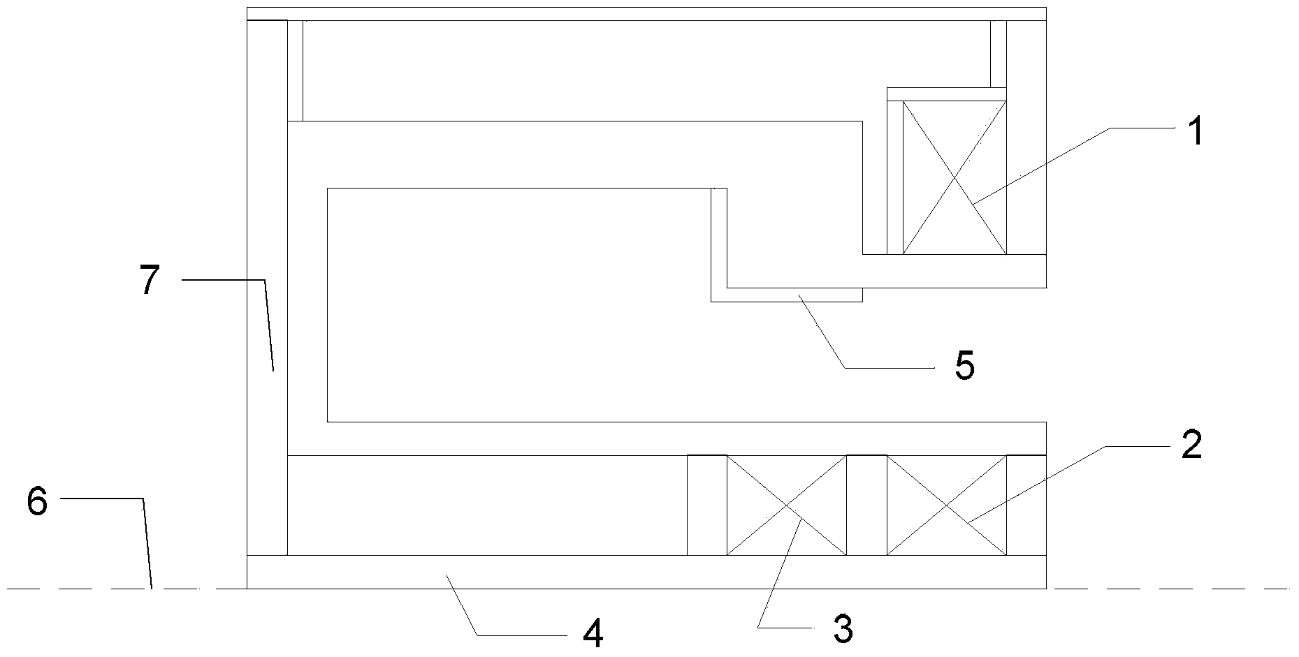
[0042] Specific implementation mode one: the following combination figure 1 , figure 2 , Figure 5 and Figure 6 Describe this embodiment, the method for determining the percentage range of the ampere-turn change of the coil according to the dynamic magnetic field associated with the coupling oscillation in the Hall thruster described in this embodiment, the two-dimensional symmetrical model of the Hall thruster includes the outer coil 1, the inner coil 2. Additional coil 3, inner magnetic pole 4, anode 5, base plate 7, which has an axis of symmetry 6,

[0043] Coil ampere-turn change percentage range is the ampere-turn change percentage range of the outer coil 1, the ampere-turn change percentage range of the inner coil 2 or the ampere-turn change percentage range of the additional coil 3;

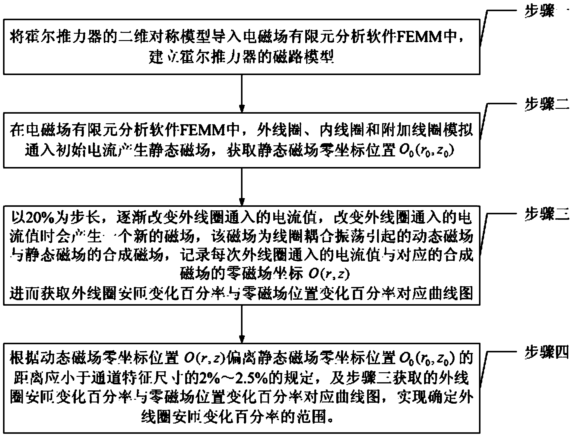
[0044] The method for determining the percentage range of the ampere-turn change of the outer coil 1 includes the following steps:

[0045] Step 1. Import the two-dimensional symmetr...

specific Embodiment approach 2

[0056] Specific implementation mode two: the following combination figure 1 , image 3 , Figure 5 and Figure 7 To illustrate this embodiment, the two-dimensional symmetrical model of the Hall thruster described in this embodiment includes an outer coil 1, an inner coil 2, an additional coil 3, an inner magnetic pole 4, an anode 5, and a base plate 7, which has an axis of symmetry 6,

[0057] Coil ampere-turn change percentage range is the ampere-turn change percentage range of the outer coil 1, the ampere-turn change percentage range of the inner coil 2 or the ampere-turn change percentage range of the additional coil 3;

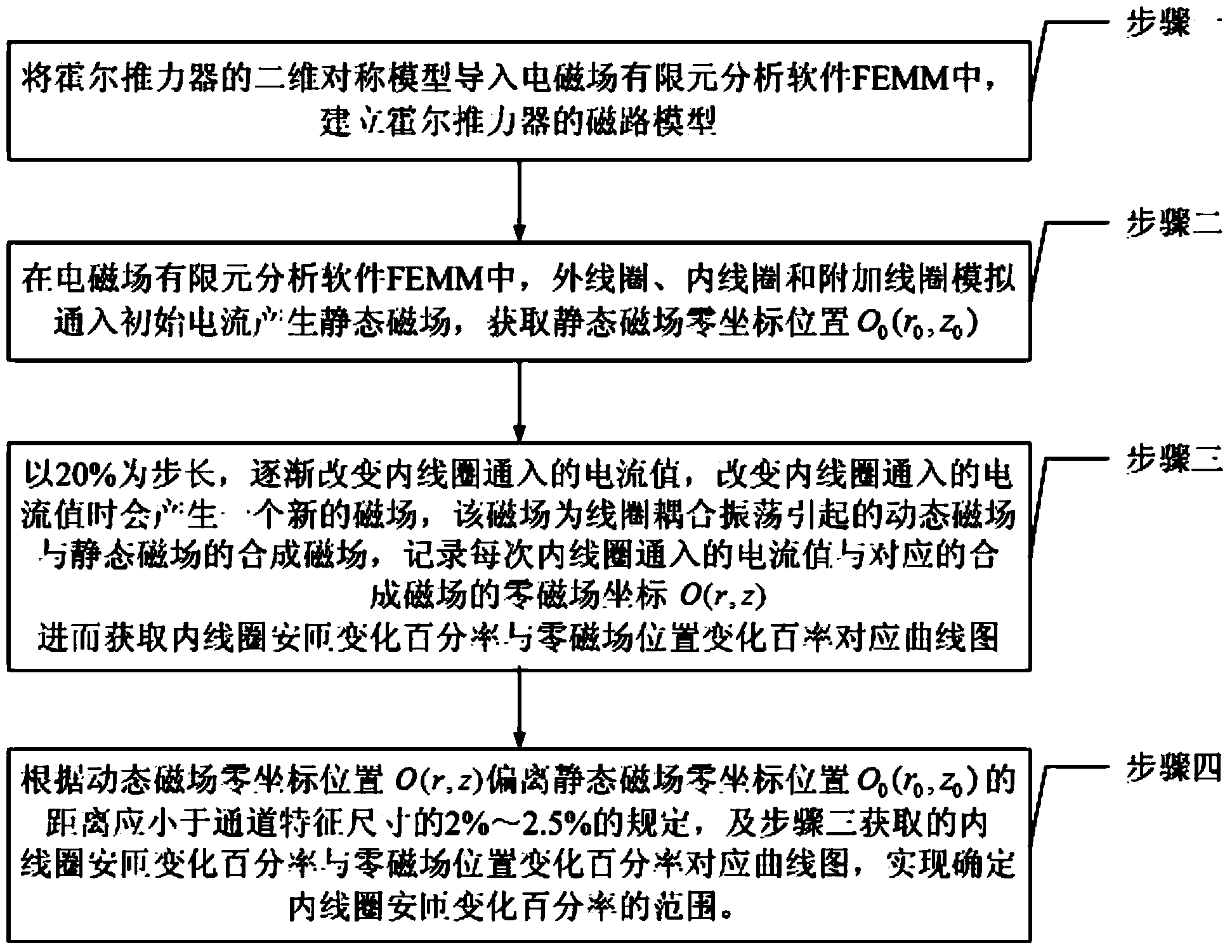
[0058] The method for determining the percentage range of the ampere-turn variation of the inner coil 2 includes the following steps:

[0059] Step 1. Import the two-dimensional symmetrical model of the Hall thruster into the electromagnetic field finite element analysis software FEMM, establish the magnetic circuit model of the Hall thruster, and estab...

specific Embodiment approach 3

[0067] Specific implementation mode three: the following combination figure 1 , image 3 , Figure 5 and Figure 8 Describe this embodiment, the method for determining the percentage range of the ampere-turn change of the coil according to the dynamic magnetic field associated with the coupling oscillation in the Hall thruster described in this embodiment, the two-dimensional symmetrical model of the Hall thruster includes the outer coil 1, the inner coil 2. Additional coil 3, inner magnetic pole 4, anode 5, base plate 7, which has an axis of symmetry 6,

[0068] Coil ampere-turn change percentage range is the ampere-turn change percentage range of the outer coil 1, the ampere-turn change percentage range of the inner coil 2 or the ampere-turn change percentage range of the additional coil 3;

[0069] The method for determining the percentage range of the ampere-turn change of the additional coil 3 includes the following steps:

[0070] Step 1. Import the two-dimensional s...


PUM


Abstract

The invention discloses a method for determining the ampere-turn change percentage range of a coil according to a dynamic magnetic field associated with coupled oscillation in a Hall thruster, belongs to the field of aerospace aviation, and aims to solve the problem of inaccurate ampere-turn change percentage range of the coil of the Hall thruster determined by using a static magnetic field. The method comprises the following steps: I, importing a two-dimensional symmetrical model of the Hall thruster into an FEMM to build a magnetic circuit model; II, introducing initial current into three coils in a simulating manner to generate a static magnetic field, and acquiring the zero coordinate position of the static magnetic field; III, gradually changing the value of current introduced into one of the coils at the step length of 20 percent to obtain a corresponding curve graph of the ampere-turn change percentage of the coil and the zero magnetic field position change percentage; IV, determining the range of the ampere-turn change percentage of an outer coil according to the specification that the deviation distance between the zero coordinate position of the dynamic magnetic field and the zero coordinate position of the static magnetic field is 2-2.5 percent lower than the channel feature size and the step III.

Description

technical field [0001] The invention relates to a method for determining operating parameters of a Hall thruster, and belongs to the field of aerospace. Background technique [0002] It has become a trend in the field of aerospace propulsion that electric propulsion devices replace chemical thrusters with their advantages of high efficiency and high specific impulse. Hall thruster is a kind of electric propulsion device. It has become an important power device for spacecraft such as satellites and probes due to its advantages of high efficiency, long working life, high power density, and moderate specific impulse. The Hall thruster generates thrust through the Hall effect, and the magnetic field is the key to generate the Hall effect. Therefore, the Hall thruster must be designed with an appropriate magnetic field to increase the ionization rate, increase the plasma density, and effectively confine the behavior of the plasma. The magnetic field of the Hall thruster is usua...

Claims


Application Information

Patent Timeline
Patent Type & Authority Applications(China)
IPC IPC(8): G01R33/12
Inventor 杨子怡魏立秋韩亮于达仁
Owner HARBIN INST OF TECH
Why Eureka
Try Eureka