
A control system and method for a liquid flow battery system

A flow battery and control system technology, applied in fuel cells, circuits, electrical components, etc., can solve the problems of reducing the stack efficiency of the flow battery system, increasing self-discharge, and low rated power status, so as to reduce capacity loss , reduced quantity, and strong capacity retention

Active Publication Date: 2016-03-30
DALIAN RONGKE POWER
View PDF7 Cites 0 Cited by
  • Summary
  • Abstract
  • Description
  • Claims
  • Application Information

AI Technical Summary

Problems solved by technology

In a flow battery system in which stacks are connected in parallel, the electrolyte must flow through each stack to achieve power output, but in reality, the output of the flow battery system is not always at the rated power state, and in many cases is half the rated power At this time, the electrolyte in the system still has to pass through each stack in series-parallel combination, and the power of each stack is in a low rated power state, which not only reduces the The efficiency of the system stack, and each stack flows into the electrolyte, which increases the self-discharge phenomenon caused by the cross-channel migration of the electrolyte through the ion-exchange membrane

Method used


Image

  • A control system and method for a liquid flow battery system
  • A control system and method for a liquid flow battery system

Examples


Embodiment Construction

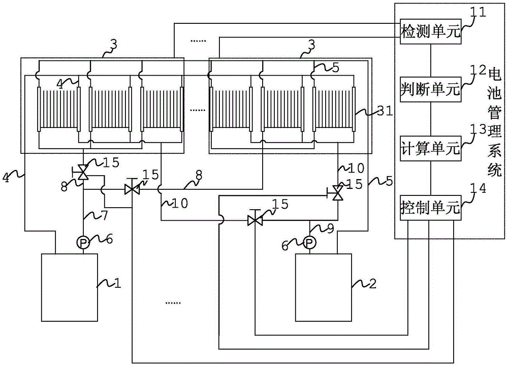
[0033] Such as figure 1 A control system of a liquid flow battery system is shown, and the liquid flow battery system includes: a positive electrode electrolyte storage tank 1, a negative electrode electrolyte storage tank 2, and a plurality of electric stacks 3 connected in parallel; each electric stack The positive electrode electrolyte outlet of 3 is connected to the positive electrode electrolyte storage tank 1 through the positive electrode electrolyte outflow pipeline 4, and the negative electrode electrolyte solution outlet of each stack group 3 is connected to the negative electrode electrolyte storage tank through the negative electrode electrolyte outflow pipeline 5. The tank 2 is connected; the positive electrolyte storage tank 1 is connected to the positive electrolyte inlet of each stack group 3 through the positive electrolyte inflow pipeline through the circulation pump 6; the negative electrolyte storage tank 2 is passed through the negative electrode through th...


PUM


Abstract

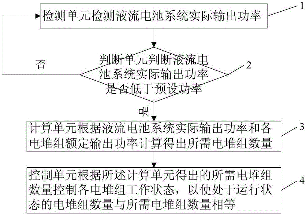
The invention discloses a control system and a control method of a flow battery system. The control system comprises a battery management system which is connected with a plurality of galvanic pile groups. The battery management system comprises a detection unit, a judging unit, a calculation unit and a control unit, wherein the detection unit is used for detecting actual output power of the flow battery system; the judging unit is used for judging whether the actual output power of the flow battery system is lower than a preset power or not; the calculation unit is used for calculating the quantity of the needed galvanic pile groups according to the actual output power of the flow battery system and rated output power of each galvanic pile group when the actual output power of the flow battery system is lower than the preset power; the control unit is used for controlling the work state of each galvanic pile group so as to enable the quantity of the galvanic pile groups under the running state to be equal to that of the needed galvanic pile groups. By adopting the control system and the control method, not only can the efficiency of the flow batter system be improved, but also the service life and efficiency of the galvanic pile groups can always stay at an optimal state, the electrolyte is unnecessary to flow into each galvanic pile, and the self-discharging phenomenon caused by the playing and migration of electrolyte when passing an ion exchanging membrane can be reduced.

Description

technical field [0001] The invention relates to the field of liquid flow batteries, in particular to a control system and method for a liquid flow battery system. Background technique [0002] Due to its long life, high safety, strong overcharge and overdischarge capabilities, and environmental friendliness, flow batteries have become one of the ideal choices for large-scale energy storage. Its main application markets include renewable energy power stations and user-side smart microgrids. (residential areas, industrial areas, public facilities), etc. Correspondingly, the main functions of the liquid flow battery system include peak peak use, load balancing, and power quality improvement. [0003] A flow battery system is generally composed of a combination of several stacks, and the combination of each stack is not simply connected in series. Factors such as the matching of battery voltage, current and energy storage inverter, and the optimization of system leakage current ...

Claims


Application Information

Patent Timeline
Patent Type & Authority Patents(China)
IPC IPC(8): H01M8/04992H01M8/04313
CPCH01M8/04619H01M8/188Y02E60/50
Inventor 张宇张华民杨振坤马相坤王晓丽李颖
Owner DALIAN RONGKE POWER
Learn More