Control system and control method of unit power factor single-stage ac-dc isolation converter

A unit power factor, isolated converter technology, applied in the control/regulation system, DC power input into DC power output, AC power input into DC power output and other directions, can solve the problem of high cost, low conversion efficiency, control circuit complex issues

Active Publication Date: 2017-03-08
SHANDONG UNIV
View PDF3 Cites 0 Cited by
  • Summary
  • Abstract
  • Description
  • Claims
  • Application Information

AI Technical Summary

Problems solved by technology

This type of AC-DC isolated converter adopts two-stage high-frequency conversion, that is, PFC high-frequency conversion and isolated DC-DC high-frequency conversion, which reduces the conversion efficiency, because these two high-frequency conversions require two sets of control systems with different functions , so it has the disadvantages of complex control circuit and high cost

Method used


Image

  • Control system and control method of unit power factor single-stage ac-dc isolation converter
  • Control system and control method of unit power factor single-stage ac-dc isolation converter
  • Control system and control method of unit power factor single-stage ac-dc isolation converter

Examples


Embodiment 1

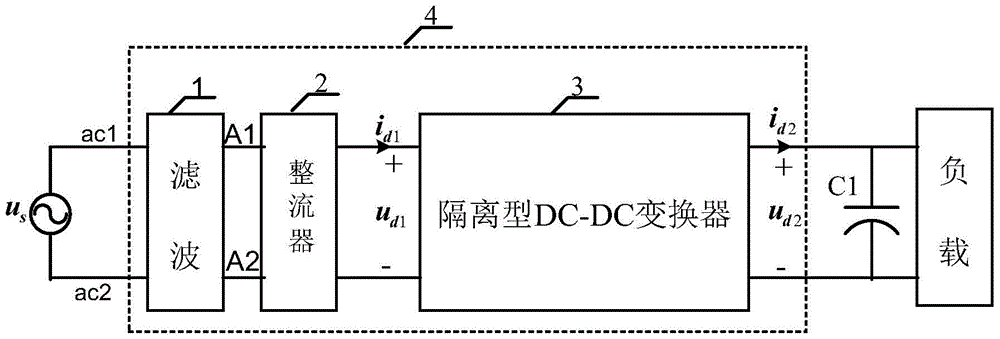
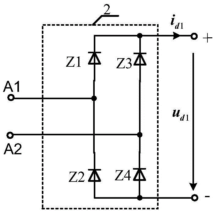
[0072] figure 2 The rectifier 2 in the image 3 Realization, DC-DC isolated converter 3 by Figure 5 Realization constitutes a unidirectional unit power factor single-stage full-bridge AC-DC isolation converter main circuit topology, and its power is transmitted from the input AC side (AC) side to the DC side load (ie figure 2 , power is transmitted from left to right). Primary side DC bus current i d1 The detection can be used to detect the switching tube current i s2 and i s4 or i s1 and i s3 Substituted after addition, the secondary side DC bus current i d2 The detection can be used to detect the switching tube current i s6 and i s8 Substitute after addition.

Embodiment 2

[0074] figure 2 The rectifier 2 in the Figure 3a Realization, DC-DC isolated converter 3 by Figure 5a Realization constitutes a unidirectional unit power factor single-stage full-bridge grid-connected DC-AC isolation converter main circuit topology, and its power is transmitted from the DC side (DC) load to the input AC side (AC) side (ie figure 2 , power is transmitted from right to left). Primary side DC bus current i d1 The detection can be used to detect the switching tube current i s2 and i s4 Substituted after addition, the secondary side DC bus current i d2 The detection can be used to detect the switching tube current i s6 and i s8 or i s5 and i s7 Substitute after addition.

Embodiment 3

[0076] figure 2 The rectifier 2 in the image 3 Realization, DC-DC isolated converter 3 by Figure 6 Realization constitutes a unidirectional unit power factor single-stage half-bridge type AC-DC isolation converter main circuit topology, and its power is transmitted from the input AC side (AC) side to the DC side load (ie figure 2 , power is transmitted from left to right).


PUM


Abstract

The invention discloses a system and method for controlling a unit power factor single-level AC-DC converter. The system comprises a composite controller, and the composite controller receives a secondary side direct current bus voltage and current signal and a secondary side direct current reference voltage and current signal of the single-level AC-DC isolation converter and converts the received voltages and the currents into an effective alternating current reference value. The effective alternating current reference value and the voltage value are calculated through a multiplying unit into a primary side current reference signal, and the primary side current reference signal, a primary side current signal, a primary side voltage signal and a secondary side voltage signal are input into a current controller. According to the system and method, both-way and single-level AC-DC or DC-AC isolation converting can be achieved, the system is conveniently used in battery charging / discharging or photovoltaic grid connection generating, the cascading modularization single-level isolation AC-DC conversion can be achieved, and the system serves as a power electronic transformer to be applied to high-voltage alternating current input application occasions.

Description

technical field [0001] The invention relates to the technical field of power electronic conversion, in particular to an isolated single-stage AC-DC isolated converter with a unit power factor and a control method thereof. Background technique [0002] The AC-DC isolated converter is generally composed of a rectifier and an isolated DC-DC converter. This type of AC-DC converter has a low power factor because a large-capacity filter capacitor needs to be connected in parallel after the rectifier. In order to improve the power factor, in the prior art, a power factor correction (Power Factor Correction, PFC) circuit is generally added between the rectifier and the isolated DC-DC converter, such as figure 1 shown. This type of AC-DC isolated converter adopts two-stage high-frequency conversion, that is, PFC high-frequency conversion and isolated DC-DC high-frequency conversion, which reduces the conversion efficiency, because these two high-frequency conversions require two set...

Claims


Application Information

Patent Timeline
Patent Type & Authority Patents(China)
IPC IPC(8): H02M7/04H02M7/219H02M3/335
CPCY02E10/56
Inventor 王广柱王明达李峰张勋王婷
Owner SHANDONG UNIV
Why Eureka
Try Eureka