
Two-way allowance-variable milling method for blade

A blade and allowance technology, applied in milling machine equipment, details of milling machine equipment, metal processing equipment, etc., can solve problems such as poor accuracy

Active Publication Date: 2014-08-20
西安三航动力科技有限公司
View PDF6 Cites 15 Cited by
  • Summary
  • Abstract
  • Description
  • Claims
  • Application Information

AI Technical Summary

Problems solved by technology

[0005] In order to overcome the deficiencies of the poor accuracy of the existing blade variable margin milling method, the present invention provides a blade bidirectional variable margin milling method

Method used


Image

  • Two-way allowance-variable milling method for blade
  • Two-way allowance-variable milling method for blade
  • Two-way allowance-variable milling method for blade

Examples


Embodiment Construction

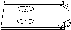
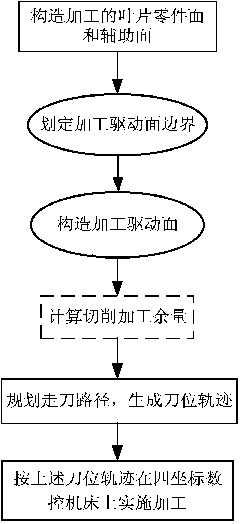
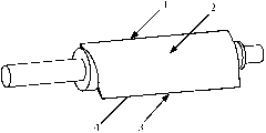
[0030] The following examples refer to Figure 1-6 .

[0031] Taking the thin-walled guide blade of an aero-engine as an example, the size of the blade is 60mm×25mm×1.5mm, and the diameter of the tool is 6mm. First construct the part surface and auxiliary surface of the processed blade, then delineate the boundary of the machining driving surface, construct the machining driving surface, calculate the cutting machining allowance, plan the tool path, and generate the tool position trajectory. Finally, according to the above tool position trajectory in four Machining is performed on a coordinate CNC machine tool. The blade is processed by a four-axis CNC machining center. The axial direction of the blade coincides with the X-axis of the machine tool and can rotate 360° around the X-axis. Specific steps are as follows:

[0032] Step 1: Construct the 3D model of the blade in the 3D modeling software UG according to the blade design data given by the design department; The pot...


PUM


Abstract

The invention discloses a two-way allowance-variable milling method for a blade. The method is used for solving the technical problem that an existing allowance-variable milling method for the blade is low in accuracy. According to the technical scheme, firstly, a three-dimensional blade model is established in three-dimensional modeling software UG; both the two end faces of the blade are made deflect towards a blade body in the three-dimensional blade model, so that two deflection faces, namely, the blade root edge interface and the blade tip edge interface, are obtained; a driving face is determined by means of a section line lofting method; then, machining routes on the driving face are determined; allowance of each machining route is determined by means of a lever allowance fine tuning method; finally, circulation machining is conducted on the blade according to the set allowance, so that machining accuracy is improved for the blade. According to the method, when the blade with the length which is about 70 mm is machined, the surface tolerance of the blade can be controlled within the range of 0.06 mm to 0.1 mm.

Description

technical field [0001] The invention relates to a blade variable margin milling method, in particular to a blade bidirectional variable margin milling method. Background technique [0002] The blade is one of the core components of the aero-engine, and it is also a typical thin-walled part. Its manufacturing level directly affects the aerodynamic performance of the aero-engine. The proportion of various types of blades in aero-engine manufacturing is about 30%. The performance of an aero-engine depends largely on the design and manufacturing level of the blade profile. The functional mission of the blade in the engine and its working characteristics determine that the blade is the part of the engine with complex shape, large size span, severe force and maximum load. It operates under high temperature, high pressure and high speed, and usually needs to be made of materials such as titanium alloys, aluminum alloys and superalloys with a high degree of alloying. In order to ...

Claims


Application Information

Patent Timeline
Patent Type & Authority Applications(China)
IPC IPC(8): B23C3/18
Inventor 单晨伟刘维伟蔺小军田荣鑫任军学王增强廖恺
Owner 西安三航动力科技有限公司
Learn More