
Barrel contained solidified waste grease discharging device

A barrel-packed waste oil technology, which is applied in the field of barrel-packed condensed waste oil discharge device, can solve the problems of increased oil-water separation, heavy maintenance workload, and easy damage to the vibrating machine, so as to improve the effect and meet the production requirements. Effect

Active Publication Date: 2014-08-20
LONGYAN ZHUOYUE NEW ENERGY CO LTD
View PDF5 Cites 1 Cited by
  • Summary
  • Abstract
  • Description
  • Claims
  • Application Information

AI Technical Summary

Problems solved by technology

The disadvantages of this method are: ①The speed of oil pouring is slow, and the production efficiency is low; ②The waste of steam is large, and part of the steam can not be fully utilized, and the energy consumption is high; ③Directly heated by steam, the condensed water in the steam and the waste oil are partially emulsified, It increases the difficulty of oil-water separation, which affects the biodiesel methylation reaction in the subsequent process; ④ part of the steam carries the odor of waste oil and disperses in the production workshop, affecting the working environment; ⑤ It is easy to be burned by steam during operation, and sometimes the steam will break through the bottom of the barrel people, there is a security risk
For this reason, the top cover of the iron oil barrel was completely broken first, then inverted and vibrated to discharge the waste oil, but there were still problems such as slow oil discharge, easy damage to vibrator and other equipment, heavy maintenance workload, and low equipment integrity rate. defect

Method used


Image

  • Barrel contained solidified waste grease discharging device
  • Barrel contained solidified waste grease discharging device
  • Barrel contained solidified waste grease discharging device

Examples


Embodiment Construction

[0021] The barrel-packed solidified waste oil outlet device of the present invention will be further described in detail below in conjunction with the accompanying drawings and specific embodiments.

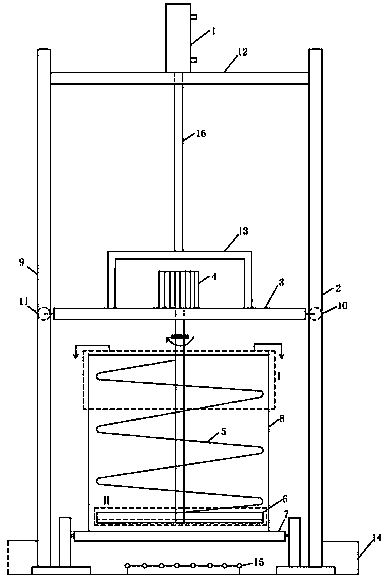
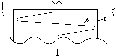
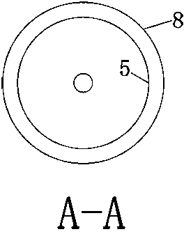
[0022] Figure 1 to Figure 6 The barreled condensed solid waste oil outlet device of the present invention as shown includes a hydraulic cylinder 1, a right side concave groove guide rail 2, a lower fixed beam 3, a motor 4, a screw auger 5, a scraper 6, a chain conveyor 7, and a left side concave groove. shaped groove guide rail 9, right side guide wheel 10, left side guide wheel 11, upper fixed beam 12, connector 13 and hydraulic rod 16; the two ends of the upper fixed beam 12 are respectively fixed on the right side concave groove guide rail 2 and the left side On the side concave groove guide rail 9, the hydraulic cylinder 1 is installed on the upper fixed beam 12, and the hydraulic rod 16 is connected with the lower fixed beam 3 by a connecting piece 13, which is in the shape...


PUM


Abstract

The invention discloses a barrel contained solidified waste grease discharging device which comprises a hydraulic oil cylinder, a concave groove guide rail, a lower fixing beam, a motor, a spiral auger, a scraper, guide wheels, an upper fixing beam and a connecting piece. The two ends of the upper fixing beam are fixed to the concave groove guide rail, the hydraulic oil cylinder is mounted on the upper fixing beam, and the hydraulic rod is connected with the lower fixing beam through the connecting piece. The motor is fixed to the lower fixing beam, the shaft of the motor is connected with the spiral auger, and one scraper which is inclined downwards and forms an angle between 25 degrees to 50 degrees with the horizontal level is mounted on the bottom of the spiral auger. The guide wheels are mounted at the two ends of the lower fixing beam, the hydraulic rod pushes the connecting piece to drive the lower fixing beam, the motor, and the spiral auger and the scraper to move up and down along the concave groove guide rail through the guide wheels. The barrel contained solidified waste grease discharging device is efficient in production, low in energy consumption, free of pollution, safe to operate, high in rate of equipment in good conditions and small in maintenance working load, and subsequent work procedures are not influenced.

Description

technical field [0001] The invention relates to a discharge device for materials in a container, in particular to a barrel-packed solidified waste oil discharge device. Background technique [0002] The production of biodiesel uses waste oil such as waste oil and hog oil as the main raw materials, and the waste oil is generally packaged and transported in recycled iron oil drums with a volume of 200 liters. In industrial production, the waste oil is first sampled and analyzed, and then the barreled waste oil that meets the quality requirements is poured into the production line. Since the barrel mouth of the oil barrel is small, when the waste oil is semi-condensed or solidified, pour it out from the mouth of the barrel The waste grease is slow or cannot be poured out from the mouth of the barrel at all. At this time, steam needs to be introduced from the mouth of the barrel to heat, melt and flow out. The disadvantages of this method are: ①The oil pouring speed is slow, an...

Claims


Application Information

Patent Timeline
Patent Type & Authority Applications(China)
IPC IPC(8): B65G65/34
Inventor 叶活动罗丹明罗敏健
Owner LONGYAN ZHUOYUE NEW ENERGY CO LTD
Learn More