Pavement milling apparatus

A milling machine and milling cutter technology, which is applied in the field of road milling machines, can solve the problems of single function of milling unit, incompetence, time-consuming and laborious replacement, etc.

Active Publication Date: 2014-08-20
SHANDONG VANSE MECHANICAL TECH CO LTD
View PDF6 Cites 5 Cited by
  • Summary
  • Abstract
  • Description
  • Claims
  • Application Information

AI Technical Summary

Problems solved by technology

[0003] The milling device works in conjunction with the sliding form mold. During the paving construction, different mold shapes must be changed according to the requirements of different road surface designs. The direction of soil discharge also changes with the different construction conditions. The milling width also changes accordingly, so it is necessary to replace the milling cutter wheels with different widths and functions to meet different needs. The known milling unit has a single function and is time-consuming and laborious to replace, and it is difficult to do it under special working conditions.

Method used


Image

  • Pavement milling apparatus
  • Pavement milling apparatus
  • Pavement milling apparatus

Examples


Embodiment 1

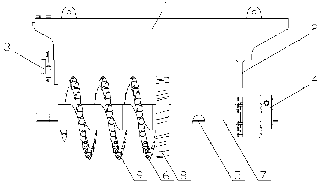
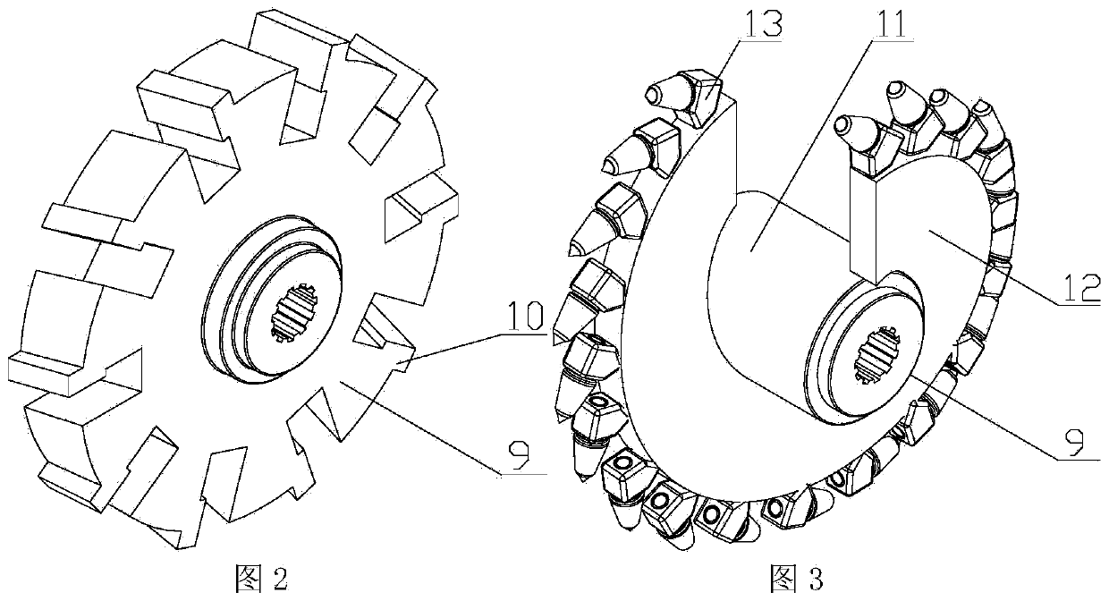
[0025] Embodiment 1: as figure 1 As shown, the road surface milling device includes a main bracket 1, a motor fixing plate 2 is provided on one side of the bottom of the main bracket 1, and a tool adjustment clamping plate 3 is movable on the other side of the bottom of the main bracket 1, and a motor fixing plate 2 is provided on the other side of the bottom of the main bracket 1. A drive motor 4 is provided on the top, and the drive motor 4 is an electric motor; a spline shaft 5 is coaxially fixed on the output shaft of the drive motor 4, and the top of the spline shaft 5 passes through the tool adjustment clamp 3, and the spline shaft 5 The upper sleeve is equipped with a milling cutter wheel 6 and a limit sleeve 7. The limit sleeve 7 enables the milling cutter wheel 6 to be positioned accurately on the spline shaft 5 and does not move when working; the drive motor 4 passes through the spline shaft 5 Drive the milling cutter wheel 6 to rotate; the milling cutter wheel 6 inc...

Embodiment 2

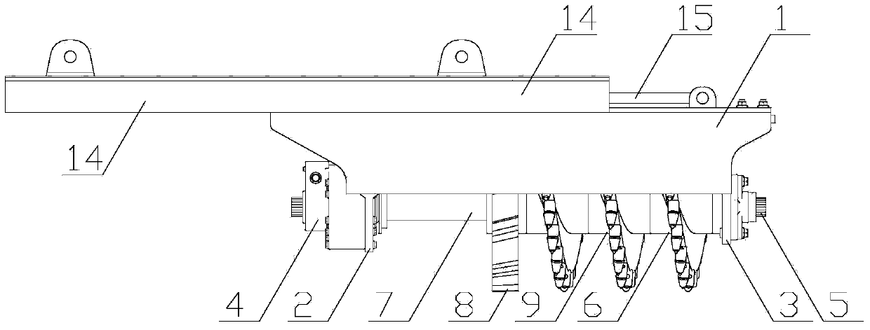
[0026] Embodiment 2: as Figure 4 to Figure 6 As shown, the road milling device includes a main support 1 and a telescopic adjustment plate 14; a motor fixing plate 2 is provided on one side of the bottom of the main support 1, and a cutter adjustment clamping plate 3 is movable on the other side of the bottom of the main support 1 , a drive motor 4 is arranged on the motor fixing plate 2, and the drive motor 4 is an electric motor; a spline shaft 5 is coaxially fixed on the output shaft of the drive motor 4, and the top end of the spline shaft 5 passes through the cutter adjustment clamping plate 3 , a milling cutter wheel 6 and a limit sleeve 7 are set on the spline shaft 5, and the limit sleeve 7 enables the milling cutter wheel 6 to be positioned accurately on the spline shaft 5, and will not move when working; the drive motor 4. Drive the milling cutter wheel 6 to rotate through the spline shaft 5; the milling cutter wheel 6 includes a side cutter milling cutter wheel 8 a...

Embodiment 3

[0027] Embodiment 3: as Figure 8 to Figure 11 As shown, the road milling device includes a main support 1 and two telescopic adjustment plates 14; a motor fixing plate 2 is provided on one side of the bottom of the main support 1, and a tool adjustment clamping plate is movable on the other side of the bottom of the main support 1 3. A drive motor 4 is provided on the motor fixing plate 2, and the drive motor 4 is a hydraulic motor; a spline shaft 5 is coaxially fixed on the output shaft of the drive motor 4, and the top of the spline shaft 5 passes through the tool adjustment clamping plate 3. A milling cutter wheel 6 and a limit sleeve 7 are set on the spline shaft 5. The limit sleeve 7 enables the milling cutter wheel 6 to be positioned accurately on the spline shaft 5 and does not move when it is working; The motor 4 drives the milling cutter wheel 6 to rotate through the spline shaft 5; the milling cutter wheel 6 includes a side cutter milling cutter wheel 8 and three ea...


PUM


Abstract

A disclosed pavement milling apparatus comprises a milling-apparatus main support; one side of the bottom of the main support is provided with a motor fixing plate, and the other side of the bottom of the main support is flexible provided with a cutter adjusting clamping plate; a driving motor is arranged on the motor fixing plate; the output shaft of the driving motor is coaxially fixedly provided with a spline shaft; the top of the spline shaft penetrates the cutter adjusting clamping plate; and the spline shaft is sleeved by milling cutter wheels and a limit casing pipe. The pavement milling apparatus has the advantages that milling apparatuses with different width can be obtained through combination according to user demands, cutter wheels are easy and convenient to replace, the dumping direction and the direction for cutting edges of a reference layer are selectable, cut reference-layer edges are tidy, and because two employed cutter wheels have different structures and are used to specifically process pavement, the cutting resistance is reduced and milling and ditching operations are steady.

Description

Technical field: [0001] The invention relates to a pair of matching equipment for a slip form paver, in particular to a road surface milling device. Background technique: [0002] The known milling device of slip mode cement concrete paver (slip form paver for short) configuration is a spiral milling device, [0003] The milling device works in conjunction with the sliding form mold. During the paving construction, different mold shapes must be changed according to the requirements of different road surface designs. The direction of soil discharge also changes with the different construction conditions. The milling width of the milling unit also changes accordingly, so it is necessary to replace the milling cutter wheel with different widths and functions to meet different needs. The known milling unit has a single function and is time-consuming and laborious to replace, and it is difficult to do it under special working conditions. Invention content: [0004] The purpose...

Claims


Application Information

Patent Timeline
Patent Type & Authority Applications(China)
IPC IPC(8): E01C23/088
Inventor 陈建军
Owner SHANDONG VANSE MECHANICAL TECH CO LTD
Why Eureka
Try Eureka