Adjustable steel beam in-place mounting device

An adjustable steel girder technology, which is applied in construction, building construction, and building material processing, can solve problems such as increasing the workload and cost of processing plants or construction sites, increasing the workload of high-altitude fire contact, and affecting construction efficiency. , to achieve the effect of avoiding high-altitude cutting and hot work, facilitating batch processing and production, and improving construction safety

Inactive Publication Date: 2014-08-20
CHINA CONSTR STEEL STRUCTURE JIANGSU CO LTD
View PDF5 Cites 12 Cited by
  • Summary
  • Abstract
  • Description
  • Claims
  • Application Information

AI Technical Summary

Problems solved by technology

Using this method to install steel beams in place requires welding in-place plates at both ends of each steel beam, which increases the investment in manpower, materials, and equipment, and increases construction costs; Due to the existence of slabs, the stacking of steel girders and steel girders cannot effectively ensure stability, which increases the investment in transportation and fixing measures and affects transportation safety; after installation, it must be cut before subsequent construction of the floor bearing slab, which limits the construction sequence of each process , to increase the construction period, and at the same time, high-altitude cutting operations are required, which increases the workload of high-altitude fire contact, especially the cutting of the in-place plates at both ends of the column-to-column steel beams, which involves hot work near the edge, and there are great safety hazards. The cutting of the bit plate may cause damage to the steel beam, resulting in material loss and affecting the structural safety
[0004] It can be seen from the introduction of the above-mentioned prior art on the installation and construction of steel beams that the existing in-place technology has at least the following problems: (1) increasing the workload and cost of the processing plant or construction site; (2) affecting the components transportation; (3) affecting construction efficiency; (4) affecting construction safety; (5) affecting component quality

Method used


Image

  • Adjustable steel beam in-place mounting device
  • Adjustable steel beam in-place mounting device
  • Adjustable steel beam in-place mounting device

Examples


Embodiment Construction

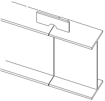
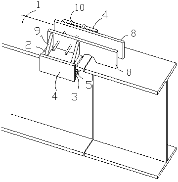
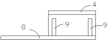
[0030] see figure 2 — Figure 5 , the present invention relates to a device for installing an adjustable steel beam, including a U-shaped jacket, an adjustment assembly, a pull bolt 10 and a seating plate 8, and the U-shaped jacket is formed by an upper splint 2 and a lower splint 3 through a vertical The plate 4 is welded, and a clamping groove that can accommodate the flange plate of the steel beam is formed between the upper splint 2 and the lower splint 3, and an adjusting bolt hole is provided on the lower splint 3; the adjusting assembly includes a backing plate 5, an adjusting Screw rod 7, adjusting nut 6, the backing plate 5 is arranged between the upper splint 2 and the lower splint 3 of the U-shaped jacket through the adjusting screw 7 and the adjusting nut 6, and the adjusting screw 7 and the backing plate 5 are welded by a perforated plug ; The seating plate 8 is a rectangular slat with a pull bolt hole, which is welded with the upper splint 2 of the U-shaped jac...


PUM


Abstract

The invention discloses an adjustable steel beam in-place mounting device, and belongs to the field of steel structure engineering construction. The device comprises a U-shaped clamp sleeve, an adjusting component, a split bolt and an in-place plate. The U-shaped clamp sleeve is formed by welding an upper clamping plate and a lower clamping plate through a vertical plate, a clamping groove capable of containing a steel beam flange plate is formed between the upper clamping plate and the lower clamping plate, and an adjusting bolt hole is formed in the lower clamping plate. The adjusting component comprises a base plate, an adjusting screw rod and an adjusting nut, and the base plate is arranged between the upper clamping plate and the lower clamping plate of the U-shaped clamp sleeve, and is connected with the U-shaped clamp sleeve through the adjusting screw rod and the adjusting nut. The in-place plate is a rectangular plate strip with a split bolt hole, and is in welding connection with the upper clamping plate of the U-shaped clamp sleeve. The device is suitable for in-place mounting of various common steel beams with an H-shaped section or I-shaped steel beams, and the hosting speed of the steel beams is effectively improved. Damage caused by welding and cutting of the in-place plate to base metal is avoided, meanwhile, material consumption is reduced, and construction cost is saved.

Description

technical field [0001] The invention relates to an adjustable steel girder installation device suitable for steel structure construction. It belongs to the field of steel structure building construction. Background technique [0002] With the acceleration of urbanization in our country, the upsurge of investing in the construction of high-rise buildings continues to heat up all over the country, and high-rise buildings have sprung up one after another, becoming local landmarks. The construction of these high-rise buildings mostly adopts the core tube-steel frame structure system. The steel frame is usually composed of steel columns and steel beams, and the steel beams are mostly H-shaped or I-shaped. Installation efficiency, but the processing of beam-column and beam-beam connection nodes has not been able to effectively improve efficiency. [0003] An existing technology such as figure 1 As shown, the steel beam is temporarily placed in place by welding the positioning p...

Claims


Application Information

Patent Timeline
Patent Type & Authority Applications(China)
IPC IPC(8): E04G21/18
Inventor 郑洋陈韬颜冬王超赵龙生陈刚徐丹陈冬杰
Owner CHINA CONSTR STEEL STRUCTURE JIANGSU CO LTD
Why Eureka
Try Eureka