Rotating inclined disc type compressor

A swash plate and compressor technology, applied in the field of compressors, can solve the problems of reducing discharge pressure, increasing compressor power consumption, pressure imbalance, etc., and achieving the effects of reducing noise, reducing pulsation, and reducing pulsating pressure

Active Publication Date: 2014-08-20
ANHUI DYNE AUTO AIR CONDITIONER LTD
View PDF10 Cites 5 Cited by
  • Summary
  • Abstract
  • Description
  • Claims
  • Application Information

AI Technical Summary

Problems solved by technology

[0005] 1. Refrigerant gas circulates in the suction chamber of the front cylinder head, the crankshaft chamber and the suction chamber of the rear cylinder head, so that there is a pressure imbalance in these three chambers, which easily leads to early wear of the moving parts of the compressor
[0006] 2. Since there is a valve plate device between the rear cylinder head and the rear cylinder, and the suction passage inside the valve plate is provided with long bolts for connection, so that the suction passage is narrow and long, this structure hinders refrigeration The flow of agent gas will eventually cause pressure loss
[0007] 3. Since the refrigerant gas will collide with the inner wall of the suction channel during the circulation process, it will cause the gas to fluctuate and cause noise, which will also increase the power consumption of the compressor
The exhaust passage is extended, which makes the discharge of refrigerant gas unstable, the discharge pressure is reduced, and noise is also generated

Method used


Image

  • Rotating inclined disc type compressor
  • Rotating inclined disc type compressor
  • Rotating inclined disc type compressor

Examples


Embodiment Construction

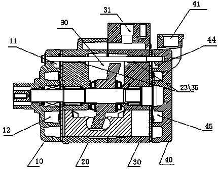
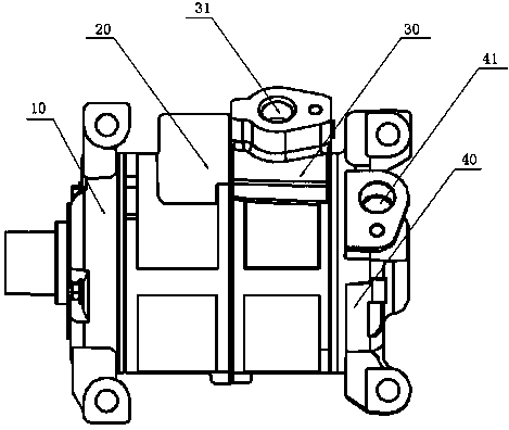
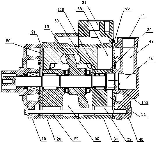
[0042] like figure 2 , 3 As shown, a suction device of a swash plate compressor includes a front cylinder 20, a rear cylinder 30 and a crank chamber 90 connected to each other, and a front cylinder head 10 and a rear cylinder for closing the ends of the front and rear cylinders. Cover 40, the front cylinder head 10 is connected with the front cylinder 20 through the front valve plate 50, the rear cylinder 30 is connected with the rear cylinder head 40 through the rear valve plate 60; The refrigerant suction port 41 on the outer surface of the rear cylinder head 40 . The swash plate 70, the bearing 110 and the piston 80 are arranged in the front and rear cylinders.

[0043]Preferably, the air intake stabilizing area 100 is formed inside the connection between the rear cylinder head 40 and the rear cylinder 30 .

[0044] The second situation is that the structure is the same as above, except that the exhaust port 31 of the refrigerant is located on the outer surface of the f...


PUM


Abstract

The invention provides a rotating inclined disc type compressor. A gas suction expansion portion is arranged in the middle of a rear cover exhaust cavity. A rear cover gas suction passageway communicated with a gas suction opening is located inside the gas suction expansion portion. The outlet end of the expansion portion is communicated with a gas suction pressure stabilization area. A main expansion passageway communicated with the gas suction pressure stabilization area is arranged in a rear cylinder. The main expansion passageway is communicated with a rear cylinder gas suction passageway through auxiliary expansion passageways. The rear cylinder gas suction passageway is communicated with a rear cover gas suction cavity and a crank cavity. A front cylinder gas suction passageway communicated with the crank cavity is formed in a front cylinder. The front cylinder gas suction passageway is communicated with a front cover gas suction cavity of a front cylinder cover. Gas refrigerating fluid simultaneously enters the rear cover gas suction cavity of the rear cylinder cover, the crank cavity and the front cover gas suction cavity of the front cylinder cover after passing through the auxiliary expansion passageways in the rear cylinder in the gas suction process. The gas refrigerating fluid is sucked through the auxiliary expansion passageways step by step, and therefore the sucked gas refrigerating fluid is made more stable, and gas pulsation and noise are effectively reduced.

Description

technical field [0001] The invention relates to the technical field of compressors, in particular to a swash plate compressor. [0002] Background technique [0003] The compressor is the heart of the refrigeration system. It inhales low-temperature and low-pressure refrigerant gas from the suction pipe, drives the piston to compress it through the operation of the motor, and discharges high-temperature and high-pressure refrigerant gas to the exhaust pipe to provide power for the refrigeration cycle. Thus realizing the refrigeration cycle of compression→condensation (heat release)→expansion→evaporation (heat absorption). The compressor widely used in automobiles is a swash plate compressor, which relies on the rotary motion of the swash plate inclined to a certain extent to the rotating shaft to drive the piston or piston rod to reciprocate to realize gas compression. [0004] The swash plate compressor is mainly composed of a swash plate, two cylinders assembled on the s...

Claims


Application Information

Patent Timeline
IPC IPC(8): F04B27/12F04B39/00
Inventor 方益万建峰王刚
Owner ANHUI DYNE AUTO AIR CONDITIONER LTD
Why Eureka
Try Eureka