led optical system and lamps

An optical system and light technology, applied in light sources, planar light sources, semiconductor devices of light-emitting elements, etc., can solve problems such as glare of lamps and low optical utilization of lamps

Active Publication Date: 2017-10-03
SHENZHEN INST FOR INNOVATIVE DESIGN CO LTD
View PDF11 Cites 2 Cited by
  • Summary
  • Abstract
  • Description
  • Claims
  • Application Information

AI Technical Summary

Problems solved by technology

[0005] Based on this, it is necessary to provide an LED optical system and a lamp for solving the problem of low optical utilization of the lamp due to the glare problem of the lamp.

Method used


Image

  • led optical system and lamps
  • led optical system and lamps
  • led optical system and lamps

Examples


Embodiment Construction

[0025] In order to facilitate the understanding of the present invention, the present invention will be described more fully below with reference to the associated drawings. Preferred embodiments of the invention are shown in the accompanying drawings. However, the present invention can be embodied in many different forms and is not limited to the embodiments described herein. On the contrary, these embodiments are provided to make the understanding of the disclosure of the present invention more thorough and comprehensive.

[0026] It should be noted that when an element is referred to as being “fixed” to another element, it can be directly on the other element or there can also be an intervening element. When an element is referred to as being "connected to" another element, it can be directly connected to the other element or intervening elements may also be present.

[0027] Unless otherwise defined, all technical and scientific terms used herein have the same meaning as...


PUM


Abstract

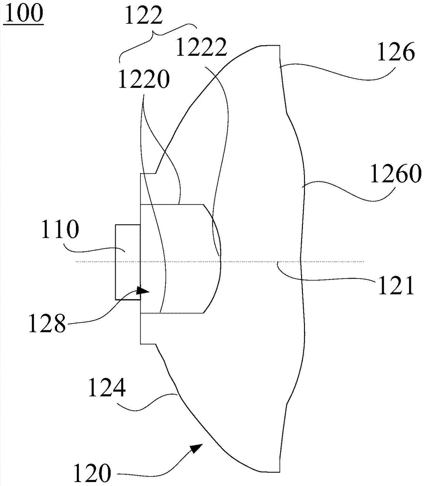
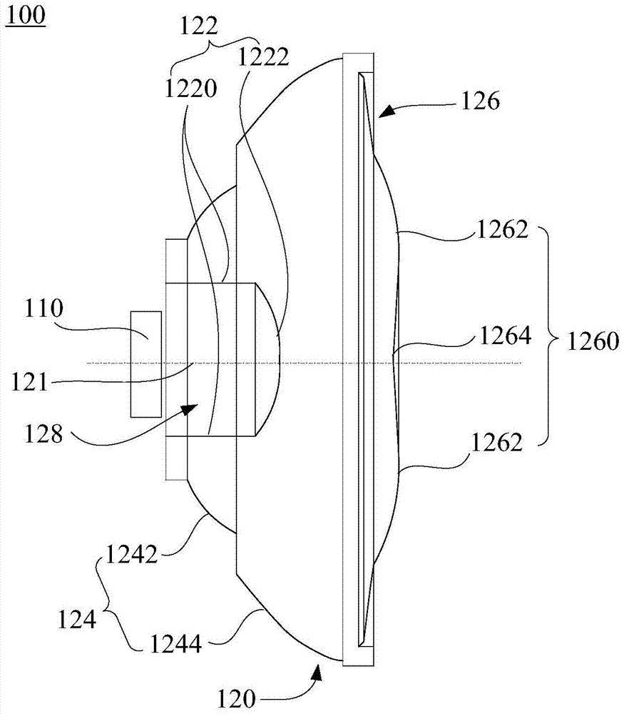
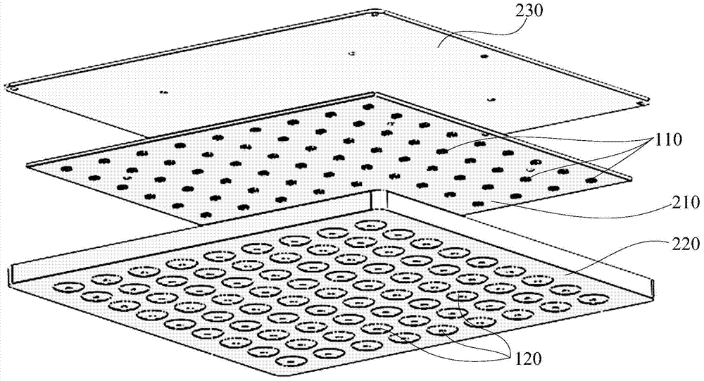
An LED optical system comprises a light emitting element and an anti-glare substrate. The anti-glare substrate comprises a light entering surface, a reflecting surface and a light emitting surface. The light entering surface faces the light emitting element, the reflecting surface is located between the light entering surface and the light emitting surface, and the orthographic projection, towards the light emitting surface, of the light entering surface and the orthographic projection, towards the light emitting surface, of the light emitting surface are located on the light emitting surface. The light emitting surface comprises a light emitting sub-surface which is a curved surface, and the light emitting sub-surface is located on the central region of the light emitting surface and protrudes away from the light entering surface. The light emitting surface comprises the light emitting sub-surface which is the curved surface, the light emitting sub-surface is located on the central region of the light emitting surface and protrudes away from the light entering surface, and therefore light located on the central region can be scattered and emitted and light nearby the central axis is weakened. Light emitted out of the light emitting surface after being reflected by the reflecting surface can compensate for the light nearby the central axis, a point light source is converted into a multi-surface light source to be emitted under the premise that the optical utilization rate is sufficient, the anti-glare purpose is achieved, and reliability is high.

Description

technical field [0001] The invention relates to the technical field of lighting equipment, in particular to an LED optical system and a lamp. Background technique [0002] A light-emitting diode (Light-Emitting Diode, LED) is a semiconductor electronic component capable of emitting light. With its energy saving, environmental protection, long life and other characteristics, LED has been widely used in various indications, displays, architectural landscape lighting and other fields. Especially the LED indoor lighting series, because of its small size, high energy efficiency, easy modification, long life and other advantages, it is more and more widely used. [0003] Generally, in actual lighting applications, due to the luminous characteristics of the light source of the LED lighting, the concentrated light will produce strong glare. Glare refers to the visual condition in which there is extreme brightness contrast in space or time due to unsuitable brightness distribution ...

Claims


Application Information

Patent Timeline
Patent Type & Authority Patents(China)
IPC IPC(8): F21V5/04F21V7/04F21K9/20F21K9/60F21Y115/10F21K9/23F21Y105/14
Inventor 赵宇波郭雅群许靖焦丽华
Owner SHENZHEN INST FOR INNOVATIVE DESIGN CO LTD
Why Eureka
Try Eureka