Steel wire rope magnetic memory on-line detection device

A detection device and wire rope technology, applied in the direction of material magnetic variables, etc., can solve problems such as easy distortion, external interference of tangential component signals, difficulty in overcoming jitter, etc., and achieve the effect of overcoming external interference, improving accuracy, and eliminating measurement blind spots

Active Publication Date: 2014-08-20
TAIYUAN UNIV OF TECH
View PDF3 Cites 21 Cited by
  • Summary
  • Abstract
  • Description
  • Claims
  • Application Information

AI Technical Summary

Problems solved by technology

At present, the characteristics of the device for online detection of steel wire rope are that it needs to magnetize the steel wire rope; it is difficult to overcome the influence of vibration; only the normal component passes through zero to judge the stress concentration area of ​​the wire rope, and the metal magnetic memory detection method judges the stress concentration area and requires the detection of magnetic flux leakage at the same time The normal phase component passes through the zero point, and the tangential component reaches the maximum signal characteristic
Many detection devices ignore the tangential component, mainly because the direction of the tangential component is not easy to determine, and the signal of the tangential component is easily distorted by external interference. In order to accurately determine the stress concentration area of ​​the wire rope, we urgently need to develop an accurate method based on the magnetic memory detection technology. On-line detection device for determining the stress concentration area

Method used


Image

  • Steel wire rope magnetic memory on-line detection device
  • Steel wire rope magnetic memory on-line detection device
  • Steel wire rope magnetic memory on-line detection device

Examples


Embodiment Construction

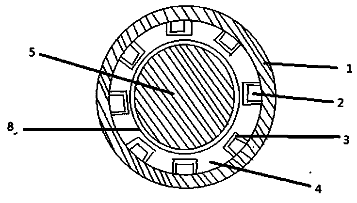
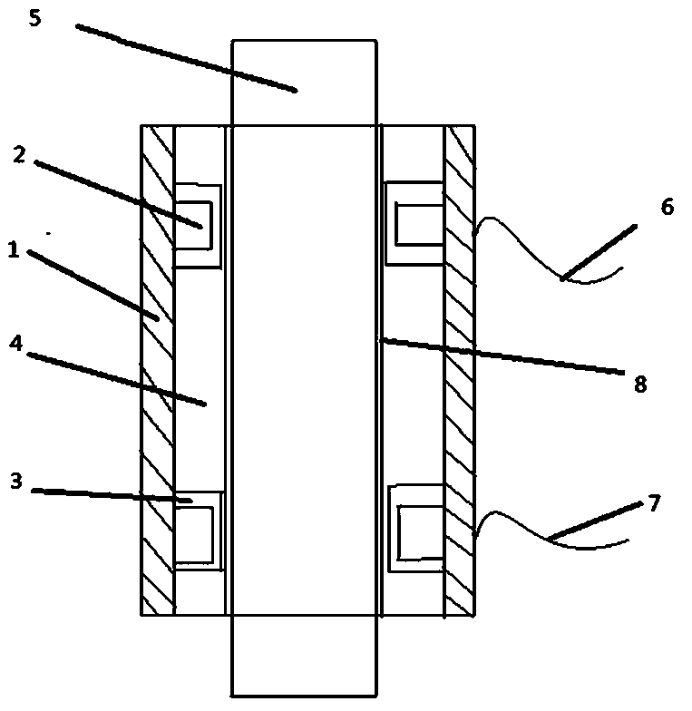
[0013] figure 1 It is a transverse sectional view of the magnetoresistive sensor of the present invention, figure 2 For the longitudinal section of the present invention, the three-dimensional magnetoresistive sensor adopts HMC1053 produced by Honeywell, its resolution is in the micro-Gauss level, and the linear error is not more than 1.8%. Two two-dimensional magnetoresistive sensors measure three-dimensional signals, improving installation convenience and reliability. The first group of magnetoresistive sensors is installed in the same direction as the second group of magnetoresistive sensors (such as Figure 5 , assuming that the sensor measurement direction is x, y, z direction, the direction of the phase component of the measurement method is the z direction, and the measurement of the tangential component is the vector synthesis of the x and y directions, then according to the pin characteristics of the three-dimensional sensor, the first group of sensors and The seco...


PUM

PropertyMeasurementUnit
Sensitivityaaaaaaaaaa

Abstract

The invention discloses a steel wire rope magnetic memory on-line detection device, and belongs to the technical field of non-destructive detection. The steel wire rope magnetic memory on-line detection device includes two groups of three-dimensional magnetoresistive sensors, adders, multipliers and subtracters, the two groups of three-dimensional magnetoresistive sensors are mounted on a steel wire rope and have the same mounting direction, and each group of three-dimensional magnetoresistive sensors comprises 8-12 three-dimensional magnetoresistive sensors uniformly distributed at a same circumference. An equilibrium and differential detection method is adopted to mainly aim to overcome steel wire rope shaking and outside interference, secondary output of signal characters is carried out, and the accuracy for judging metal member defects is improved; secondly, with adopting of a component signal single output method, whether a point is a steel wire rope defect is judged according to characteristic signals singly outputted by a normal component and a tangential component; and then, the two groups of annular uniformly-arranged three-dimensional magnetoresistive sensors HMC1053 are adopted to achieve all-dimensional inspection of the normal component and the tangential component of the steel wire rope, so as to eliminate the measured blind area problem.

Description

technical field [0001] The invention relates to a wire rope magnetic memory online detection device, which belongs to the technical field of non-destructive detection, and relates to the online non-destructive detection of the stress concentration of the wire rope, which is connected to a follow-up circuit to realize real-time dynamic flaw detection and early warning of the wire rope working online. Background technique [0002] Due to its large diameter and long length, the wire rope has a certain running speed and uneven speed during online detection, which brings challenges to the design of the online real-time detection wire rope device. The current method of detecting steel wire ropes is generally to magnetize it and then detect magnetic flux leakage, but for relatively long steel wire ropes, if it is magnetized, it will inevitably cost a higher price, and the uneven magnetization will bring great impact to the detection results. error. Once the wire rope is magnetized...

Claims


Application Information

Patent Timeline
Patent Type & Authority Applications(China)
IPC IPC(8): G01N27/83
Inventor 乔铁柱李兆星靳宝全王峰王跃龙
Owner TAIYUAN UNIV OF TECH
Why Eureka
Try Eureka