An optical module assembly and optical module
A technology of optical modules and components, which is applied in the field of optical communication, can solve the problems of downward deviation of beam optical axis, reduction of optical module coupling efficiency, deviation, etc., and achieve the effect of reducing the degree of optical axis deviation
- Summary
- Abstract
- Description
- Claims
- Application Information
AI Technical Summary
Problems solved by technology
Method used
Image
Examples
Embodiment 1
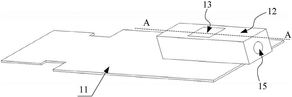
[0051] refer to Figure 2-Figure 3 The schematic diagram of the structure of the optical module is shown, and the optical module includes many components, for example: a circuit board 11 , a main component 12 , an insertion component 13 , a laser 14 and the like. In order to solve the problem of optical axis offset caused by the draft angle, the present invention mainly improves the main component 12 and the insertion component 13 in the optical module, so the embodiment of the present invention first introduces the optical module including the main component 12 and the insertion component 13 Module components.
[0052] An embodiment of the present invention provides an optical module assembly, including a main body element 12 and an insertion element 13 inserted together; wherein, the main body element 12 has a first cavity 51, and the insertion element 13 is placed in the first cavity 51 (refer to Figure 4 It can be clearly seen that in this structure), a cavity 50 is form...
Embodiment 2
[0067] An embodiment of the present invention provides an optical module, such as figure 2 , image 3 As shown, it includes: a circuit board 11, an optical module assembly, and a laser 14. Further, in order to realize the transceiver function, it may also include: a detector 18 and an optical filter 17 (in order to distinguish it from other optical filters, this optical filter is in This embodiment is hereinafter referred to as the first optical filter 17).
[0068]The circuit board 11 can generally use a PCB (Printed Circuit Board, printed circuit board). An optical module assembly is arranged on the circuit board 11, and the optical module assembly includes: a main body element 12 and an insertion element 13 inserted together, and the structure of both can refer to the first embodiment. Wherein, the main body element 12 is pasted on the circuit board 11 , and the insertion element 13 is inserted into the first cavity 51 of the main body element 12 . A first optical filte...
Embodiment 3
[0076] An embodiment of the present invention provides an optical module assembly, refer to Figure 9-Figure 10 , comprising a body element 12 and an insert element 13 inserted together; wherein, the body element 12 has a first cavity 51, and the insert element 13 is placed in the first cavity 51 (from Figure 11 It can be clearly seen in ), a cavity 50 is formed surrounded by the first cavity 51 and the insertion element 13, and the optical filter 17 can be set in the cavity 50, of course, other auxiliary optics can also be set in the cavity 50 element.
[0077] The optical module assembly is applied to the light emitting system, and the process of realizing light emission is as follows: it is located at one end of the main body element 12 ( Figure 10 The light emitted by the laser 14 at the left end of the) passes through the insertion element 13 and is coupled into the other end of the main body element 12 ( Figure 10 The right end of the) optical fiber (inserted in the...
PUM
 Abstract
Description
Claims
Application Information
 - R&D
- Intellectual Property
- Life Sciences
- Materials
- Tech Scout
- Unparalleled Data Quality
- Higher Quality Content
- 60% Fewer Hallucinations
Browse by: Latest US Patents, China's latest patents, Technical Efficacy Thesaurus, Application Domain, Technology Topic, Popular Technical Reports.
© 2025 PatSnap. All rights reserved.Legal|Privacy policy|Modern Slavery Act Transparency Statement|Sitemap|About US| Contact US: help@patsnap.com


