Open hierarchical design method for complex electronic system

A technology of electronic system and design method, which is applied in the direction of calculation, electrical digital data processing, special data processing applications, etc., to achieve the effects of convenient insertion, simplified system, and improved work efficiency

Inactive Publication Date: 2014-08-20
10TH RES INST OF CETC
View PDF4 Cites 12 Cited by
  • Summary
  • Abstract
  • Description
  • Claims
  • Application Information

AI Technical Summary

Problems solved by technology

The traditional stacking design method is difficult to adapt to the design of complex electronic systems. In order to effectively deal with large-scale, complex and highly integrated systems at the module level, new design theories and methods must be studied

Method used


Image

  • Open hierarchical design method for complex electronic system
  • Open hierarchical design method for complex electronic system

Examples


Embodiment Construction

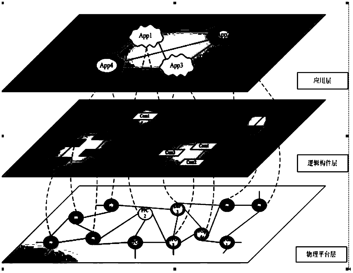
[0010] refer to figure 1 . According to the present invention, firstly, the complex electronic system is divided into three levels by adopting the layered design theory, namely the application layer, the logical component layer, and the physical platform layer.

[0011] The application layer may consist of one or more functional threads App1, App2, App3, App4.... The application layer displays various functional characteristics that complex electronic systems need to realize. These functional characteristics are represented by functional threads App1, App2, App3, App4..., and there are information between application functional threads App1, App2, App3, App4... through virtual ports. Interactive relationships.

[0012] The logical component layer is located between the application layer and the physical layer, and is composed of an interconnected logical component group composed of one or more cross-linked logical components Com1, Com2, Com3, Com4.... Each functional thread...


PUM


Abstract

The invention provides an open hierarchical design method for a complex electronic system and aims to provide a system analysis and design method for system application integration in a complex electronic system. The design method comprises the steps that firstly, the hierarchical design theory is adopted to divide the system into an application layer, a logical component layer and a physical platform layer; secondly, with regard to a specific complex electronic system application, a meta model of all levels of hardware elements and software elements and incidence relations is abstracted, and a visual modeling environment of the specific complex electronic system is established; thirdly, the complex electronic system is analyzed and decomposed in the visual modeling environment, so that a hardware model, a software model and a deployment model are established, wherein the hardware model, the software model and the deployment model are described by the meta model, and the hardware model, the software model and the deployment model are converted into function component description files and system operation blueprints; finally, all function components are respectively obtained, blueprint documents are analyzed through a control program of the complex electronic system, virtual channels between logic components are configured, and the logic components are loaded to complete the application integration of the complex electronic system.

Description

technical field [0001] The invention relates to an analysis and design method for complex electronic system integration. Background technique [0002] The so-called complex electronic system is a variety of electronic systems with different functions organically combined and coordinated to form a large and complex system with information feedback and control functions. Compared with general electronic systems, complex electronic systems have the following characteristics: Large scale and complexity: often composed of multiple interconnected and interacting subsystems, each subsystem is composed of multiple interrelated processing units. Integrity: It is required to start from the overall situation of the system and the whole process, and realize the optimization of the overall function from the interconnection of various electronic systems. Reliability: Large electronic systems are often extremely important in national defense and national economy. Its failure can have ser...

Claims


Application Information

Patent Timeline
IPC IPC(8): G06F17/50
Inventor 潘灵李典赵蕾孙德马力科
Owner 10TH RES INST OF CETC
Why Eureka
Try Eureka