Single-phase outer rotor switch reluctance generator with U-shaped stator teeth

A switched reluctance and generator technology, applied in the direction of electrical components, electromechanical devices, magnetic circuit static parts, etc., can solve the problems of large number of power switching devices, complicated stator connection, high system cost, etc., and achieve simple structure, winding The effect of easy wiring and easy installation

Inactive Publication Date: 2014-08-20
BEIJING INSTITUTE OF TECHNOLOGYGY
View PDF6 Cites 6 Cited by
  • Summary
  • Abstract
  • Description
  • Claims
  • Application Information

AI Technical Summary

Problems solved by technology

Most of the existing switched reluctance generators are high-speed generators, with an inner rotor structure, a large number of motor phases, complex stator connections, a large number of power switching devices in the power converter, and high system costs

Method used


Image

  • Single-phase outer rotor switch reluctance generator with U-shaped stator teeth
  • Single-phase outer rotor switch reluctance generator with U-shaped stator teeth
  • Single-phase outer rotor switch reluctance generator with U-shaped stator teeth

Examples


Embodiment 1

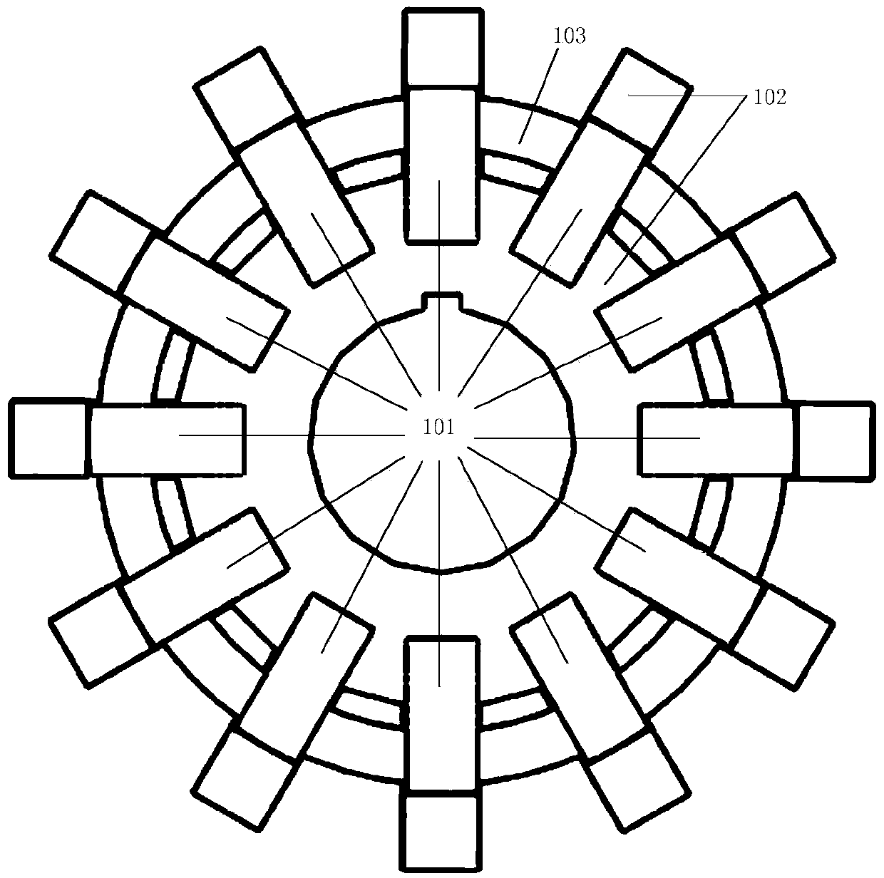
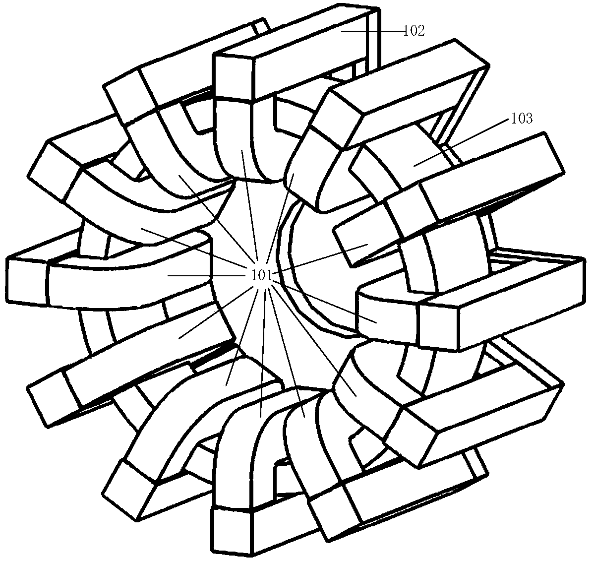
[0026] Such as figure 1 , figure 2 As shown, a single-phase U-shaped stator tooth external rotor switched reluctance generator includes a stator (101), a rotor (102) and a winding (103). The discs (104) with rectangular grooves made of non-magnetic material fix their positions with each other and are fixed on the casing (109) of the generator; The crankshaft (105) is connected; the winding (103) of the generator is a ring coil, which is wound in the U-shaped tooth groove of the stator (101); the rotor (102) is installed outside the circumference of the stator (101), and is formed by finger iron The rotor (102) has no brushes, no windings and permanent magnets, and is connected to the generator shaft (105) through a key (112). There are 12 teeth on the finger core; the generator is installed on the generator The permanent magnet (107) on the shaft (105) and the magnetic sensor (109) installed on the generator housing (108) detect the position of the rotor (102) in real time....

Embodiment 2

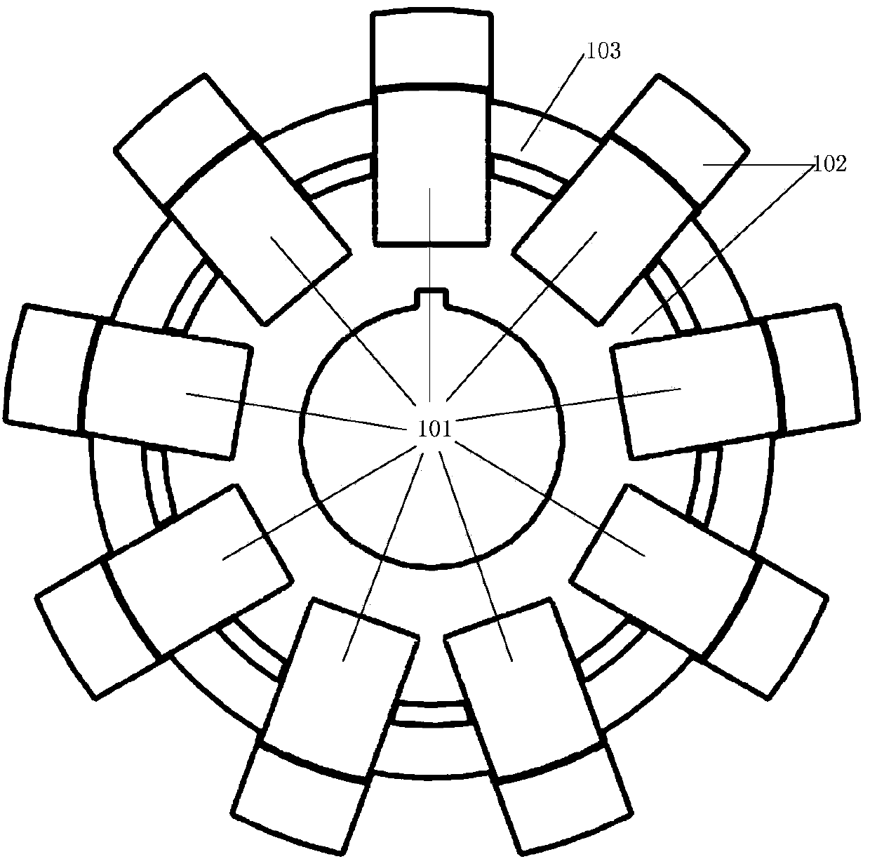
[0029] Such as image 3 , Figure 4As shown, a single-phase U-shaped stator tooth external rotor switched reluctance generator includes a stator (101), a rotor (102) and a winding (103). The discs (104) with rectangular grooves made of non-magnetic material fix their positions with each other and are fixed on the casing (109) of the generator; The crankshaft (105) is connected; the winding (103) of the generator is a ring coil, which is wound in the U-shaped tooth groove of the stator (101); the rotor (102) is installed outside the circumference of the stator (101), and is formed by finger iron The rotor (102) has no brushes, no windings and permanent magnets, and is connected with the generator shaft (105) through a key (112). There are 9 teeth on the finger core; the generator is installed on the generator The permanent magnet (107) on the shaft (105) and the magnetic sensor (109) installed on the generator casing (108) detect the position of the rotor (102) in real time. ...


PUM


Abstract

The invention provides a single-phase outer rotor switch reluctance generator with U-shaped stator teeth. The single-phase outer rotor switch reluctance generator comprises a set of mutually-independent U-shaped stator teeth, a ring winding and finger-shaped rotors, wherein the finger-shaped rotors are installed outside stator magnetic poles. Every two U-shaped stator teeth are fixed through a disk which is provided with a rectangular groove and made of non-ferromagnetic materials, and the U-shaped stator teeth are fixed to a shell of the generator. The rotors are composed of finger-shaped iron cores and connected to a shaft of the generator through keys. The number of teeth of the rotors is the same as the number of the stator teeth. The single-phase winding of the generator is an annular coil and is wound around the interior of U-shaped tooth grooves of stators. The single-phase outer rotor switch reluctance generator with the U-shaped stator teeth is simple in structure, a motor and a power converter are low in manufacturing cost, the winding can easily conduct wire winding, the increase of the number of the stator magnetic poles and the number of rotor magnetic pole of the generator cannot affect wire winding space of the winding, and the generator is more suitable for low-rotating-speed application. Magnetic fields formed in the U-shaped stator teeth are short magnetic circuits and are mutually independent and are not interlinked, and reliability of the generator is high.

Description

technical field [0001] The invention relates to a switched reluctance generator, in particular to a novel outer rotor switched reluctance generator using U-shaped stator teeth. Background technique [0002] The traditional types of wind turbines mainly include cage-type asynchronous generators, wound-type asynchronous generators, brushed doubly-fed asynchronous generators, brushless doubly-fed generators and permanent magnet synchronous generators. Although the induction motor has a relatively simple structure and low manufacturing cost, it must maintain a preset speed when generating power, requires an additional gearbox and has a limited range of wind speed for power generation. Especially the brush doubly-fed asynchronous generator has poor operation reliability and needs frequent maintenance. The permanent magnet synchronous generator does not require an external excitation device, which reduces the excitation loss; at the same time, it does not require brushes and slip...

Claims


Application Information

Patent Timeline
Patent Type & Authority Applications(China)
IPC IPC(8): H02K29/00H02K1/12H02K1/22
Inventor 冬雷
Owner BEIJING INSTITUTE OF TECHNOLOGYGY
Why Eureka
Try Eureka