Supercharge Your Innovation With Domain-Expert AI Agents!

Light-control hysteresis circuit for LED (Light-Emitting Diode) lamp

A technology of hysteresis circuit and LED lamp, which is applied in the direction of lamp circuit layout, light source, electric light source, etc., can solve the problem of LED automatic extinguishing, etc., and achieve the effect of simple circuit and reliable performance

Inactive Publication Date: 2014-08-20
刘胜泉
View PDF8 Cites 2 Cited by
  • Summary
  • Abstract
  • Description
  • Claims
  • Application Information

AI Technical Summary

Problems solved by technology

The existing light monitoring circuit has no hysteresis function, the LED light will be on and off continuously, and the light emitted by the LED light itself will cause the LED to automatically turn off

Method used


Image

  • Light-control hysteresis circuit for LED (Light-Emitting Diode) lamp
  • Light-control hysteresis circuit for LED (Light-Emitting Diode) lamp
  • Light-control hysteresis circuit for LED (Light-Emitting Diode) lamp

Examples


Embodiment Construction

[0018] The present invention will be further described below in conjunction with accompanying drawing description and specific embodiment:

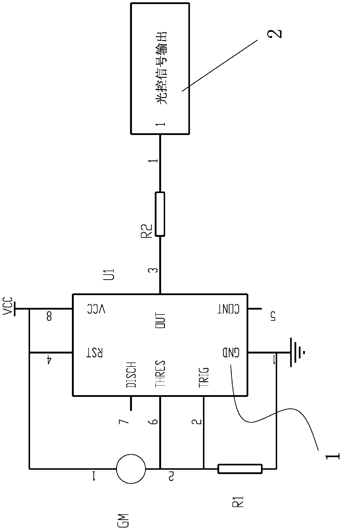
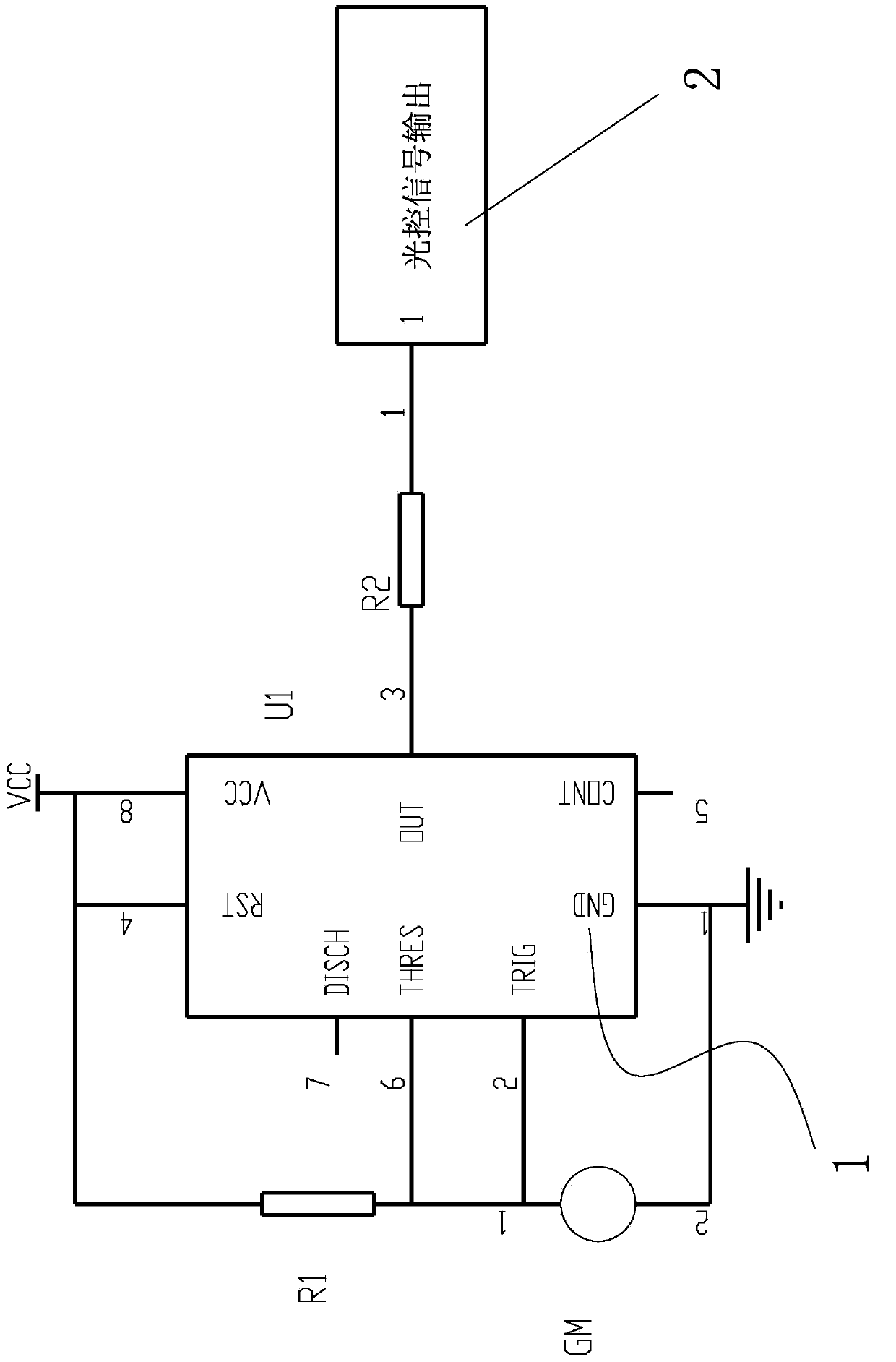
[0019] like figure 1 The shown light control hysteresis circuit for LED lights includes a delay unit 1, the delay unit 1 is connected to a photosensitive resistor GM, and the photosensitive resistor GM is connected to a light control signal output unit 2, A resistor R1 is connected to the delay unit 1 .

[0020] like figure 1 As shown, in the first embodiment of the present invention, the delay unit 1 is a time-base integrated circuit, and the resistor R1 is connected in parallel between the ground terminal GND and the trigger terminal TRIG of the time-base integrated circuit, so The photosensitive resistor GM is connected in parallel between the threshold terminal THRES and the reset terminal of the time base integrated circuit, and a resistor R2 is connected in series between the output terminal of the time base integrated circuit a...


PUM


Abstract

The invention discloses a light-control hysteresis circuit for an LED (Light-Emitting Diode) lamp. The circuit is characterized by comprising a delay unit, wherein the delay unit is connected with a photoresistor GM; the photoresistor GM is connected with a light-control signal output unit; and a resistor R1 is connected on with the delay unit. The light-control hysteresis circuit for the LED lamp aims at overcoming the defects in the prior art, and is simple in structure and reliable in performance.

Description

technical field [0001] The invention relates to a light control hysteresis circuit for LED lamps. Background technique [0002] Three-state smart LED lights, during the day or when the light is strong, the smart LED lights will automatically enter the dormant state, the LED lights will go out, and at night or when the light is weak, the LEDs will automatically turn on. In order to save energy, when the trigger condition of the electronic switch is not met, the smart LED light will be low-brightness. When the trigger condition of the electronic switch is met, the LED light will be high-brightness. The smart LED light has three working states: off, low light, and high light. [0003] Because the three-state LED smart light turns off during the day or when the light intensity is strong; at night or when the light intensity is low, the LED light turns on automatically, and when the LED light turns on automatically, the light intensity emitted by the LED light will change the re...

Claims


Application Information

Patent Timeline
IPC IPC(8): H05B37/02
CPCY02B20/42Y02B20/40
Inventor 刘胜泉
Owner 刘胜泉
Features
  • R&D
  • Intellectual Property
  • Life Sciences
  • Materials
  • Tech Scout
  • Unparalleled Data Quality
  • Higher Quality Content
  • 60% Fewer Hallucinations
Learn More