A device and method for front and back chamfering processing of porous parts

A corner processing and chamfering technology, which is applied in the field of front and back chamfering processing devices, can solve the problems of increasing the labor intensity of the operator, increasing the production cost, and operator injury, so as to improve the machining accuracy and efficiency, increase the service life, save The Effect of Tool Costs

Active Publication Date: 2017-03-29
JIANGSU GAOJING MECHANICAL & ELECTRICAL EQUIPMENT CO LTD
View PDF7 Cites 0 Cited by
  • Summary
  • Abstract
  • Description
  • Claims
  • Application Information

AI Technical Summary

Problems solved by technology

These holes often leave many sharp corners after the two processing procedures of drilling and boring. The existence of sharp corners not only causes certain difficulties in the assembly between parts, affects the assembly quality of bolted connections, but also easily causes damage to the operator. Therefore, the sharp corners on both sides of the round hole are generally chamfered to ensure the stability of the hub and the aesthetics of the hub
[0003] At present, when chamfering the round holes on the wheel hub parts, it is usually based on the requirements of the chamfering of the round holes on the parts to be added, select a drill with a suitable apex angle, and use a drilling machine to complete the chamfering processing, but the above processing methods The quality of the chamfering is not ideal. There are often burrs, vibration lines, and rough chamfering on the chamfering surface. Moreover, one clamping can only complete the processing of the side chamfering of the round hole in one direction, and the other side of the round hole. The side chamfering of the direction needs to turn the workpiece over and re-clamp it before processing
Secondly, there are often multiple round holes on the circumference of the wheel hub parts. The original drilling machine processing equipment is to process one round hole and then process the next round hole. When the hole is chamfered, it is necessary to continuously rotate the part by an angle to find the processing position of the next round hole. This operation is not only difficult, but also time-consuming and laborious.
[0004] Therefore, the following problems exist in the chamfering processing of the round holes of the wheel hub parts by the above-mentioned traditional method: 1. The processing method of chamfering the round holes in sequence, turning the workpiece over and clamping in order to process the chamfering of the two sides of the round hole in turn, the operation is very troublesome, increasing The number of tooling is reduced, the production efficiency is reduced, and the labor intensity of the operator is increased; 2. The quality requirements of the drill bits used are relatively high. If the tool wears, it will directly affect the chamfering quality of the processed workpiece. For batch-processed hub parts, Tool consumables are large, increasing production costs

Method used


Image

  • A device and method for front and back chamfering processing of porous parts
  • A device and method for front and back chamfering processing of porous parts
  • A device and method for front and back chamfering processing of porous parts

Examples


Embodiment Construction

[0039] In order to make the object, technical solution and advantages of the present invention clearer, the present invention will be further described in detail below in conjunction with the accompanying drawings and embodiments. It should be understood that the specific embodiments described here are only used to explain the present invention, not to limit the present invention. In addition, the technical features involved in the various embodiments of the present invention described below can be combined with each other as long as they do not constitute a conflict with each other.

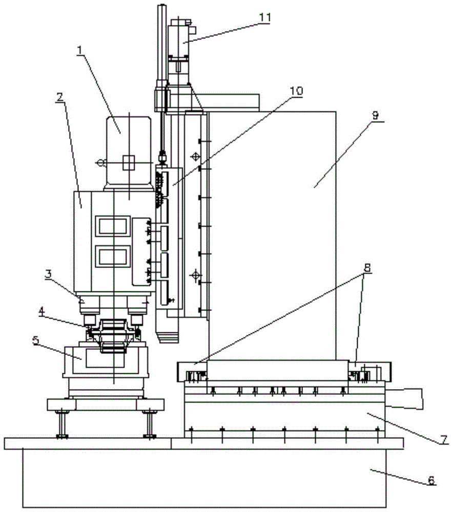
[0040] see figure 1, the porous front and back chamfering processing device of the embodiment of the present invention includes an axle box 2, a spindle box motor 1, a numerical control vertical slide table driving motor 11, a multi-axis chamfering power head 3, a workbench 5, a device base 6, and a hydraulic slide table 7. Column 9, CNC vertical slide table 10 and limit stopper 8.

[0041] Th...


PUM


Abstract

The invention discloses a front and back chamfering processing device, which comprises: a column fixedly installed on a hydraulic slide table arranged on a base, a vertical slide table fixed on a longitudinal guide rail of the column, and a vertical slide table fixedly installed on the vertical slide table On the main shaft box, the axial end face of the main shaft end is provided with a drive motor, and the other end end face is provided with a chamfering knife installed on the main shaft. The chamfering knife is fixed on the motor shaft through the knife bar, including the conductor and the blade. The cutting end of the knife body is provided with an axial plane. The axial plane is provided with a blade groove matching the shape of the blade. The blades are arranged in pairs and placed on the They are arranged in the blade groove at a certain distance in the axial direction. The invention also discloses a chamfering method using the device. The invention can realize the chamfering processing of the porous front and back surfaces at the same time in one clamping, greatly improves the chamfering processing efficiency and automation degree, reduces the working procedure and labor intensity, and solves the problem that the porous front and back surfaces cannot be chamfered at the same time .

Description

technical field [0001] The invention relates to the technical field of mechanical processing, in particular to a front and back chamfering processing device. Background technique [0002] There are many round holes on the circumference of many hub parts, such as threaded connection holes for connecting tire bolts, through holes for reducing the weight of the hub or enhancing the heat dissipation performance of the hub, etc. These holes often have certain requirements on the position. These holes often leave many sharp corners after the two processing procedures of drilling and boring. The existence of sharp corners not only causes certain difficulties in the assembly between parts, affects the assembly quality of bolted connections, but also easily causes damage to the operator. Therefore, the sharp corners on both sides of the round hole are generally chamfered to ensure the stability of the hub and the aesthetics of the hub. [0003] At present, when chamfering the round ...

Claims


Application Information

Patent Timeline
Patent Type & Authority Patents(China)
IPC IPC(8): B23D79/00
Inventor 沈大为邵新宇郑金来张永杰周伯华喻道远熊昌秀张三强戴启峰蒋勇平
Owner JIANGSU GAOJING MECHANICAL & ELECTRICAL EQUIPMENT CO LTD
Why Eureka
Try Eureka