
Elastic joint structure

An elastic and structural technology, applied in the structural field of elastic joints, can solve the problems of unfavorable force, inability to work together, and affect the durability of buildings, so as to solve the joints that are easy to crack, solve common quality problems, and solve problems that are easy to crack Effect

Inactive Publication Date: 2014-08-27
吴淑环
View PDF0 Cites 0 Cited by
  • Summary
  • Abstract
  • Description
  • Claims
  • Application Information

AI Technical Summary

Problems solved by technology

Although some structural atlases install elastic sealant at the joints, or install soft polyethylene plastic rods, but the elastic sealant and soft polyethylene plastic rods can only seal and cannot transmit internal force. If a large number of joints are installed Elastic sealant, or polyethylene plastic soft rods are also installed, and the prefabricated composite insulation boards used for the installation of the prefabricated wall or prefabricated roof cannot work together, which is not good for the force, and also affects the decoration
[0005] The above problems affect the durability of buildings and affect the process of housing industrialization
[0006] The applicant of this patent has applied for several patents on external thermal insulation walls, and now there are prefabricated walls assembled with steel wire grid cement sandwich panels, and the external plastering protective layer also has the problem of easy cracking

Method used


Image

  • Elastic joint structure
  • Elastic joint structure
  • Elastic joint structure

Examples


Embodiment approach 1

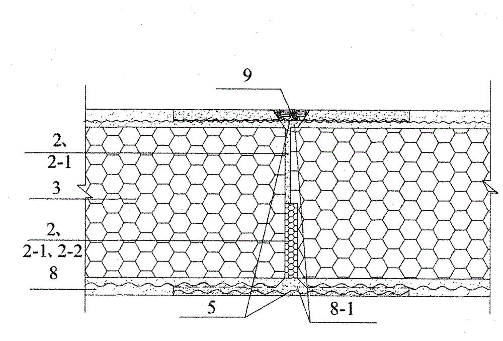
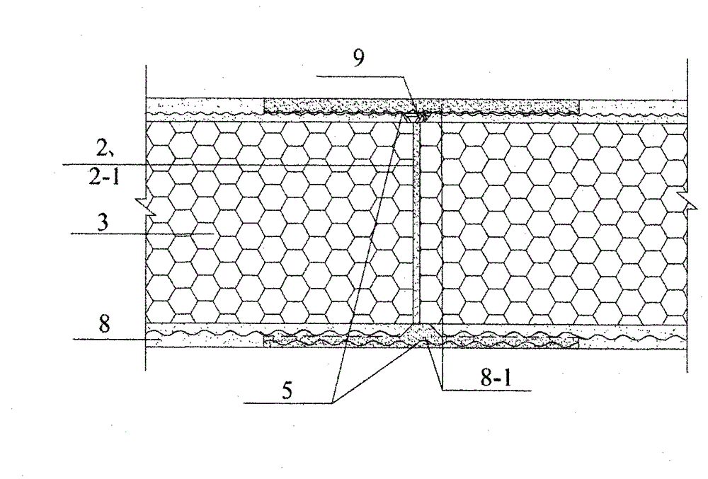
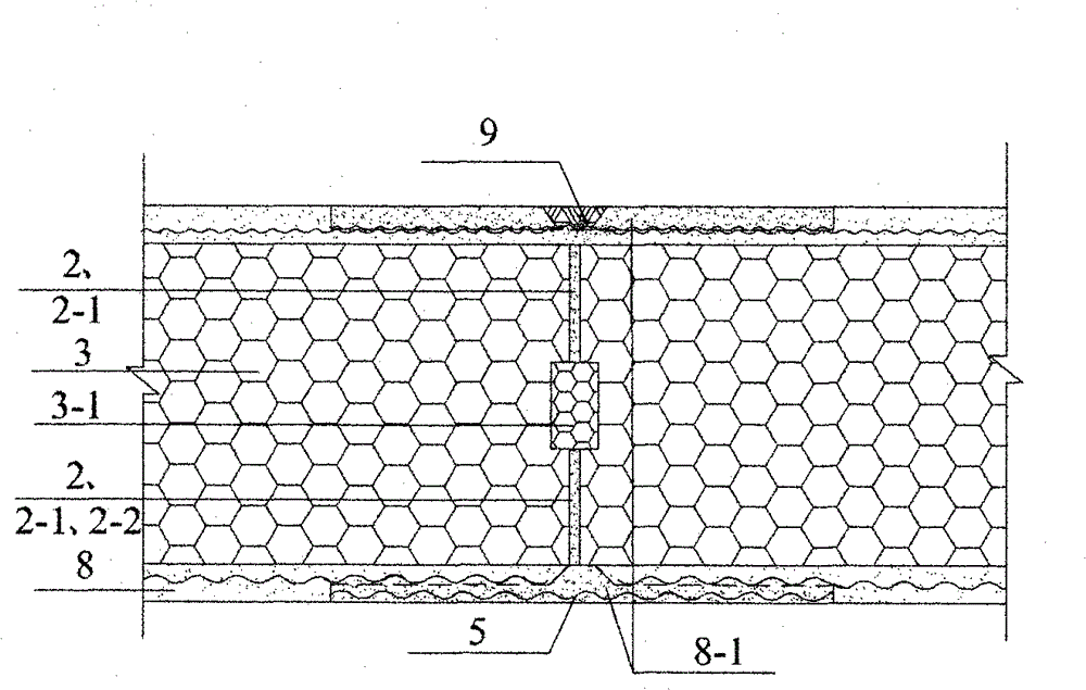
[0027] Implementation mode one: see Figure 1 ~ Figure 4 , an elastic joint structure of the present embodiment, which is composed of a prefabricated composite thermal insulation board 1 and an adhesive material 2 at the joint; The thermal insulation board 1 is adhesively connected, and the adhesive material 2 at the joint can transmit internal force, so that adjacent prefabricated composite thermal insulation panels form a common force-bearing member, and the adhesive material 2 at the joint also has the ability to adapt to a certain deformation (for example, in the The ability to deform under the action of temperature, and the ability to deform under the action of load), forming an elastic joint structure between prefabricated composite thermal insulation boards; the prefabricated composite thermal insulation board 1 is a prefabricated composite thermal insulation board of various structures.

[0028] The prefabricated composite thermal insulation board 1 is composed of a th...

Embodiment approach 2

[0030] Implementation mode two: see Figure 1 ~ Figure 4 , this embodiment provides the following elastic joint structure for reference, which is selected according to the design requirements of convenient construction and energy saving:

[0031] 1) The bonding material 2 at the joint is elastic bonding material 2-1 (such as bonding with cement polymer elastic mortar or cement polymer elastic thermal insulation mortar); or the joint is close to the side with intense temperature changes (usually the room The adhesive material 2 of the inner seam of a certain length on the outside is an elastic adhesive material 2-1, and the adhesive material 2 of the seam on the side with little temperature change (usually the indoor side) is a non-elastic adhesive material 2-2 (If the cement polymer mortar is prepared with a synthetic resin adhesive with a glass transition temperature above 0°C, there will be no elasticity); Or the prefabricated roof can adapt to temperature changes.

[0032...

Embodiment approach 3

[0041] Implementation mode three: see Figure 5 , an elastic joint structure of the present embodiment, which is composed of a base wall 10, an insulating layer 3, a cement polymer elastic mortar 8-1, a protective layer 8 and a mesh tensile material 5; the base wall 10 is a concrete wall, a brick wall, a block wall, and a lightweight filled wall with cement fiber boards and silicon-calcium boards installed on the keel; the mesh tensile material 5 is metal mesh or alkali-resistant mesh cloth or basalt fiber mesh cloth ; The thermal insulation layer 3 is installed on the base wall 10, and there is a protective layer 8 on the outside of the thermal insulation layer 3, and there is a mesh tensile material 5 in the protective layer 8;

[0042] The cement polymer elastic mortar 8-1 has bonding ability and certain ability to adapt to deformation;

[0043] The elastic joint structure is that there is a cement polymer elastic mortar 8-1 in a certain range at the outer end of the joint...


PUM


Abstract

The invention discloses an elastic joint structure, relates to a joint structure of prefabricated compound insulation plates, further relates to an elastic joint structure of external thermal insulation walls, and aims at the problem that the joint of the prefabricated compound insulation plate is easy to crack, and the problem that a protective layer of the external thermal insulation wall is easy to crack. The first structure is that the prefabricated compound insulation plates at the two sides of the joint are glued by a gluing material, and the gluing material on the joint can transfer internal force, so that the adjacent prefabricated compound insulation plates can form a shared stress component, and the gluing material on the joint further has the capability of being applicable to certain deformation; the second structure is that elastic cement polymer mortar is generated in a certain range of the outer end of an insulating layer of the external thermal insulation wall, a reticular tensile material is overlapped and glued with the insulating layer at the two sides of the joint by the elastic cement polymer mortar in a certain range, for the cement polymer mortar has gluing capacity and applicable deformability. According to the elastic joint structure provided by the invention, the common quality problem that the prefabricated compound insulation plates are likely to be cracked can be solved, good durability can be realized, and housing industrialization can be beneficially promoted.

Description

technical field [0001] The invention relates to an elastic joint structure used for installing prefabricated composite thermal insulation panels in buildings, and a structure for setting elastic joints in an external thermal insulation composite wall body. Background technique [0002] Prefabricated composite insulation board is a composite board commonly known as "sandwich board". [0003] Affected by drastic temperature changes between winter and summer and day and night, cracks are not suitable for sintered brick masonry, but other walls, including concrete walls, have troublesome cracks. [0004] Especially the problem that the joints of the prefabricated composite thermal insulation boards used for installing the prefabricated wall or the prefabricated roof are easy to crack is particularly prominent. Although some structural atlases install elastic sealant at the joints, or install soft polyethylene plastic rods, but the elastic sealant and soft polyethylene plastic r...

Claims


Application Information

Patent Timeline
IPC IPC(8): E04B1/682
Inventor 吴淑环
Owner 吴淑环
Learn More