Electronic control thermal management system for diesel engine

A thermal management system, diesel engine technology, applied in mechanical equipment, engine components, machines/engines, etc., can solve the problems of inaccurate control of cooling system temperature, unfavorable fuel consumption and emissions of diesel engines, high cooling temperature of diesel engines, etc., to reduce warm-up time , simple and reasonable structure, and the effect of prolonging life

Inactive Publication Date: 2014-08-27
GUANGXI YUCHAI MASCH CO LTD
View PDF5 Cites 19 Cited by
  • Summary
  • Abstract
  • Description
  • Claims
  • Application Information

AI Technical Summary

Problems solved by technology

[0002] The diesel engine cooling system is mainly composed of a water pump, a thermostat, a fan, a radiator, etc. The existing technical solution of the diesel engine cooling system is a thermostat in the cooling system, and the fans are all mechanically controlled. The paraffin senses the water temperature, and controls the switch and opening of the thermostat valve through the principle of thermal expansion and contraction of the paraffin. The fan is driven by the crankshaft through the pulley and the belt. The performance parameters of the thermostat and fan are fixed at the time of design. Accurately control the temperature of the cooling system according to the actual working conditions of the diesel engine and the changes in the environmental state. With the change of the working conditions and environmental conditions of the diesel engine, the cooling temperature of the diesel engine is often too high or too low, which has a negative impact on the working life of the diesel engine, diesel engine fuel consumption and emissions. negative effect

Method used


Image

  • Electronic control thermal management system for diesel engine

Examples


Embodiment Construction

[0014] The specific embodiments of the present invention will be described in detail below in conjunction with the accompanying drawings, but it should be understood that the protection scope of the present invention is not limited by the specific embodiments.

[0015] Unless expressly stated otherwise, throughout the specification and claims, the term "comprise" or variations thereof such as "includes" or "includes" and the like will be understood to include the stated elements or constituents, and not Other elements or other components are not excluded.

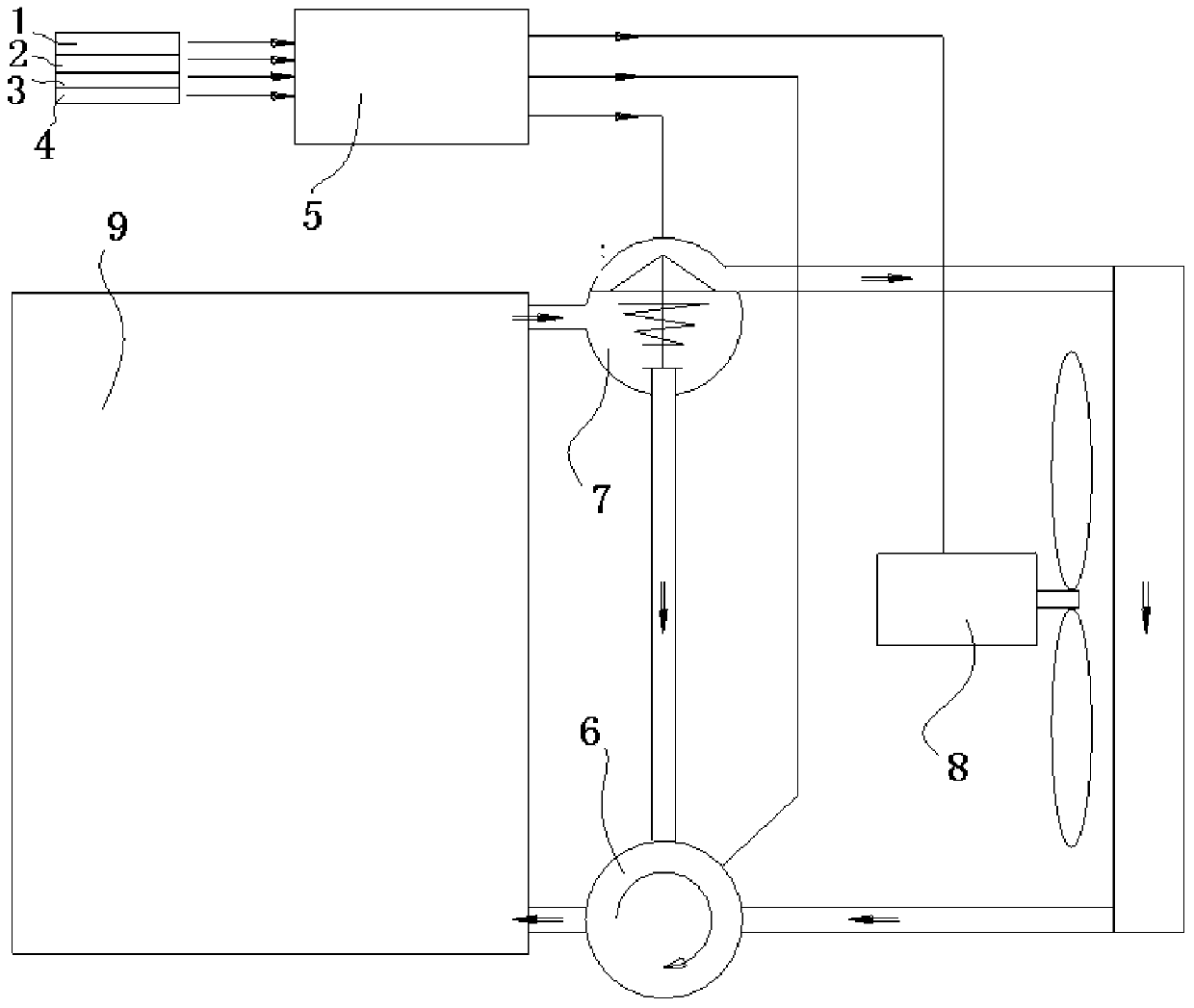
[0016] like figure 1 As shown, the specific structure of the diesel engine electronically controlled thermal management system according to a specific embodiment of the present invention includes: ECU and a speed sensor connected to the input end of the ECU, an accelerator position sensor, a temperature sensor, a pressure sensor, and an output end connected to the ECU. Electronically controlled thermostats and electronical...


PUM


Abstract

The invention discloses an electronic control thermal management system for a diesel engine. The electronic control thermal management system for the diesel engine comprises an ECU, a rotating speed sensor, an accelerator position sensor, a temperature sensor, a pressure sensor, an electronic control thermostat and an electronic control fan, wherein the temperature sensor is connected with the input end of the ECU and used for detecting the temperatures of inflow water and outflow water of a water tank of the diesel engine, the temperatures of inflow air and outflow air of an intercooler and the atmospheric temperature and sending detected data to the ECU; and the pressure sensor is connected with the input end of the ECU and used for detecting pressure of inflow air and outflow air of the intercooler of the diesel engine and atmospheric pressure and transmitting detected data to the ECU. The electronic control thermostat is connected with the output end of the ECU to enable the valve opening of the ECU to be subject to electronic control, and the electronic control fan is connected with the output end of the ECU to enable the rotating speed of the ECU to be subject to electronic control. According to the electronic control thermal management system for the diesel engine, the ECU automatically adjusts parameters of the cooling system thermostat and the fan along with changes of diesel engine working conditions and environmental states, the water temperature is always maintained around the optimal target temperature and is accurately controlled, the service life of the diesel engine is prolonged, and fuel consumption and discharge of the diesel engine are reduced.

Description

technical field [0001] The invention relates to the field of diesel engine cooling systems, in particular to an electronically controlled thermal management system for diesel engines. Background technique [0002] The diesel engine cooling system is mainly composed of a water pump, a thermostat, a fan, a radiator, etc. The existing technical solution of the diesel engine cooling system is a thermostat in the cooling system, and the fans are all mechanically controlled. The paraffin senses the water temperature, and controls the switch and opening of the thermostat valve through the principle of thermal expansion and contraction of the paraffin. The fan is driven by the crankshaft through the pulley and the belt. The performance parameters of the thermostat and the fan are fixed at the time of design. Accurately control the temperature of the cooling system according to the actual working conditions of the diesel engine and the changes in the environmental state. With the cha...

Claims


Application Information

Patent Timeline
Patent Type & Authority Applications(China)
IPC IPC(8): F01P7/16F01P7/12
Inventor 侯升田淋瑕侯伟放
Owner GUANGXI YUCHAI MASCH CO LTD
Why Eureka
Try Eureka