Efficient heat-exchange tube for evaporator
A technology of heat exchange tubes and evaporators, applied in heat exchange equipment, evaporators/condensers, tubular elements, etc., can solve problems such as partial surface tension of fluids, achieve surface tension destruction, improve heat transfer performance outside the tube, and accelerate The effect of evaporation
- Summary
- Abstract
- Description
- Claims
- Application Information
AI Technical Summary
Problems solved by technology
Method used
Image
Examples
Embodiment 1
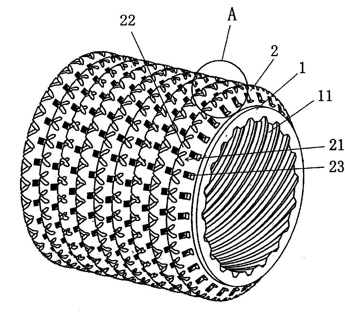
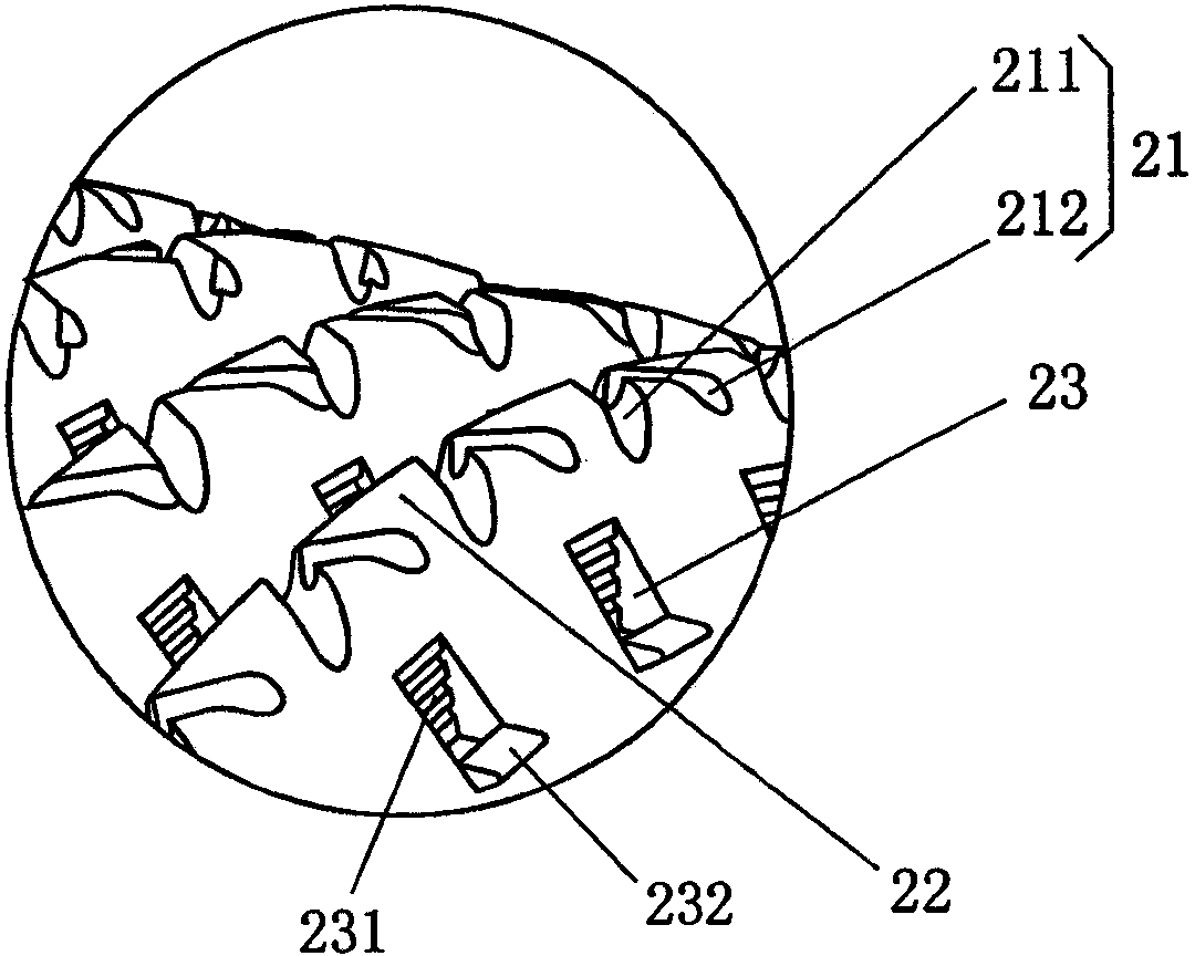
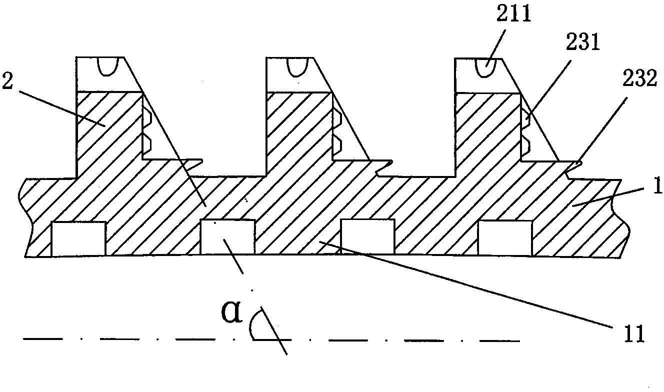
[0023] See Figure 1 to Figure 3 , provides a pipe body 1 and the material on the pipe body 1 extends along the radial direction of the pipe body 1 and extends in a spiral state around the pipe body 1 on the outer surface of the pipe body 1, and the pipe body 1 is formed as The integral outer fin 2 is formed with grooves 21 at intervals on the top of the outer fin 2 , and the area between two adjacent grooves 21 is formed as a fin platform 22 .
[0024] As the technical gist of the technical solution provided by the present invention: a half-groove 23 for enhancing heat transfer is formed in a spaced state on one side of the aforementioned outer fin 2, and the half-groove 23 faces one side of the adjacent outer fin 2. A liquid blocking groove 231 is formed on the side wall, and at the bottom of the half groove 23 in the height direction, there is formed a bubble protruding (that is, protruding) from the side surface of the outer fin 2 for controlling the volume of the bubble. ...
Embodiment 2
[0031]Half grooves 23 are formed at intervals on both sides of the outer fins 2 . Change the angle α formed between the outer fin 2 and the centerline of the tube body 1 to 135°, and change the height of the outer fin 2 to 0.5 mm. Change the pitch of the wing top grooves 211 to 1.5 mm, change the depth of the wing top auxiliary grooves 212 to 0.05 mm, and change the width of the wing top auxiliary grooves 212 to 0.05 mm. Change the height of the inner fin 11 to 0.25mm, and the helix angle to 60°. Change the depth of the top groove 211 to 0.2 mm, and the width to 0.3 mm. Change the distance between the semi-grooves 23 to 0.3 mm, the depth to 0.05 mm, and the width to 0.2 mm. Change the depth of the liquid blocking groove 231 to 0.015 mm, and the width to 0.05 mm. Change the degree to which the bubble volume control boss 232 protrudes from the side surface of the outer fin 2 to 0.05mm. The fin top groove 211 and the wing top auxiliary groove 212 form a ∧-shaped relationship ...
Embodiment 3
[0033] Half grooves 23 are formed at intervals on one side of the outer fin 2 . Change the angle α formed between the outer fin 2 and the centerline of the tube body 1 to 90°, and change the height of the outer fin 2 to 1.5 mm. Change the pitch of the wing top grooves 211 to 0.3 mm, change the depth of the wing top auxiliary grooves 212 to 0.15 mm, and change the width of the wing top auxiliary grooves 212 to 0.3 mm. Change the height of the inner fin 11 to 0.1mm, and the helix angle to 50°. Change the depth of the top groove 211 to 0.3 mm, and the width to 0.6 mm. Change the distance between the semi-grooves 23 to 1.5 mm, the depth to 0.03 mm, and the width to 1 mm. Change the depth of the liquid blocking groove 231 to 0.01 mm, and the width to 0.01 mm. Change the degree to which the bubble volume control boss 232 protrudes from the side surface of the outer fin 2 to 0.12mm. All the other are the same as the description to embodiment 1.
PUM
 Abstract
Description
Claims
Application Information
 - R&D
- Intellectual Property
- Life Sciences
- Materials
- Tech Scout
- Unparalleled Data Quality
- Higher Quality Content
- 60% Fewer Hallucinations
Browse by: Latest US Patents, China's latest patents, Technical Efficacy Thesaurus, Application Domain, Technology Topic, Popular Technical Reports.
© 2025 PatSnap. All rights reserved.Legal|Privacy policy|Modern Slavery Act Transparency Statement|Sitemap|About US| Contact US: help@patsnap.com


