High-efficiency heat exchange tube for evaporator

A technology of heat exchange tubes and evaporators, applied in heat exchange equipment, evaporators/condensers, tubular elements, etc., can solve problems such as partial surface tension of fluids, achieve surface tension destruction, improve evaporative heat transfer effects, and improve disturbance Effect

Active Publication Date: 2016-03-02
JIANGSU CUILONG PRECISION COPPER TUBE CORP
View PDF16 Cites 2 Cited by
  • Summary
  • Abstract
  • Description
  • Claims
  • Application Information

AI Technical Summary

Problems solved by technology

[0006] The above-mentioned CN100365369C, CN101776412B and CN102305569A have good positive significance for increasing the evaporation heat transfer area outside the tube so as to increase the evaporation core to facilitate the rapid growth and rapid overflow of the bubbles formed by the steam, but for the fluid disturbance to destroy the fluid surface The tension is somewhat neglected, so it is urgent to explore the effective expansion of the liquid film on the outer surface of the tube to strengthen the falling film evaporation process. For this reason, the applicant has made a positive and beneficial design, and finally formed the technical solution to be introduced below

Method used


Image

  • High-efficiency heat exchange tube for evaporator
  • High-efficiency heat exchange tube for evaporator
  • High-efficiency heat exchange tube for evaporator

Examples


Embodiment 1

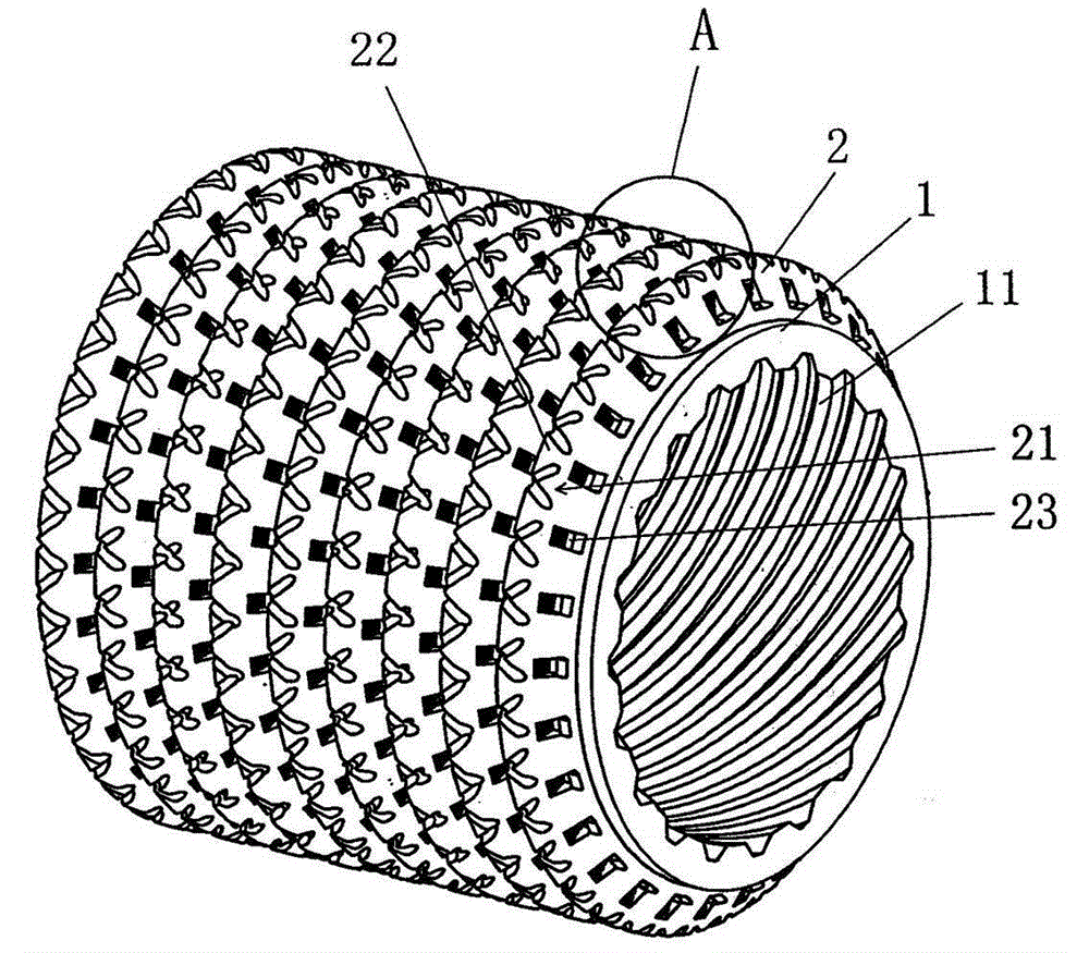
[0023] See Figure 1 to Figure 3 , provides a pipe body 1 and the material on the pipe body 1 extends along the radial direction of the pipe body 1 and extends in a spiral state around the pipe body 1 on the outer surface of the pipe body 1, and the pipe body 1 is formed as The integral outer fin 2 is formed with grooves 21 at intervals on the top of the outer fin 2 , and the area between two adjacent grooves 21 is formed as a fin platform 22 .

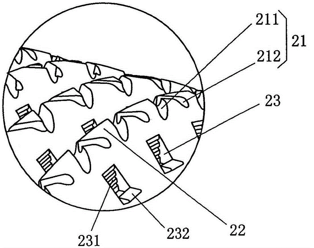
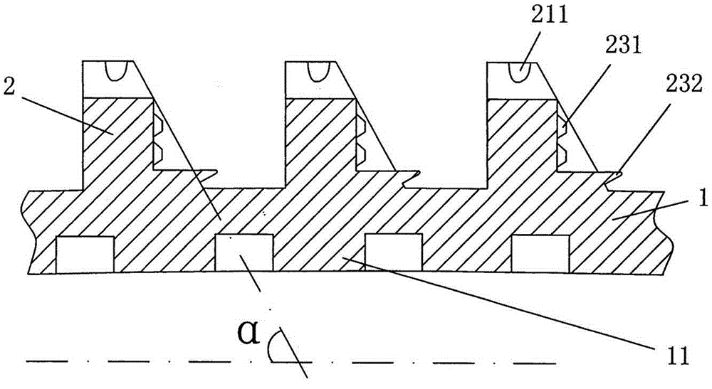
[0024] As the technical gist of the technical solution provided by the present invention: a half-groove 23 for enhancing heat transfer is formed in a spaced state on one side of the aforementioned outer fin 2, and the half-groove 23 faces one side of the adjacent outer fin 2. A liquid blocking groove 231 is formed on the side wall, and at the bottom of the half groove 23 in the height direction, there is formed a bubble protruding (that is, protruding) from the side surface of the outer fin 2 for controlling the volume of the bubble. ...

Embodiment 2

[0031]Half grooves 23 are formed at intervals on both sides of the outer fins 2 . Change the angle α formed between the outer fin 2 and the centerline of the tube body 1 to 135°, and change the height of the outer fin 2 to 0.5mm. Change the pitch of the wing top grooves 211 to 1.5 mm, change the depth of the wing top auxiliary grooves 212 to 0.05 mm, and change the width of the wing top auxiliary grooves 212 to 0.05 mm. Change the height of the inner fin 11 to 0.25mm, and the helix angle to 60°. Change the depth of the top groove 211 to 0.2 mm, and the width to 0.3 mm. Change the distance between the semi-grooves 23 to 0.3 mm, the depth to 0.05 mm, and the width to 0.2 mm. Change the depth of the liquid blocking groove 231 to 0.015 mm, and the width to 0.05 mm. Change the degree to which the bubble volume control boss 232 protrudes from the side surface of the outer fin 2 to 0.05 mm. The fin top groove 211 and the wing top auxiliary groove 212 form a ∧-shaped relationship ...

Embodiment 3

[0033] Half grooves 23 are formed at intervals on one side of the outer fin 2 . Change the angle α formed between the outer fin 2 and the centerline of the tube body 1 to 90°, and change the height of the outer fin 2 to 1.5 mm. Change the pitch of the wing top grooves 211 to 0.3 mm, change the depth of the wing top auxiliary grooves 212 to 0.15 mm, and change the width of the wing top auxiliary grooves 212 to 0.3 mm. Change the height of the inner fin 11 to 0.1mm, and the helix angle to 50°. Change the depth of the top groove 211 to 0.3 mm, and the width to 0.6 mm. Change the distance between the semi-grooves 23 to 1.5 mm, the depth to 0.03 mm, and the width to 1 mm. Change the depth of the liquid blocking groove 231 to 0.01 mm, and the width to 0.01 mm. Change the degree to which the bubble volume control boss 232 protrudes from the side surface of the outer fin 2 to 0.12mm. All the other are the same as the description to embodiment 1.


PUM


Abstract

The invention provides an efficient heat-exchange tube for an evaporator, and belongs to the technical field of evaporation heat-exchange tubes in air conditioner and refrigerating systems. The efficient heat-exchange tube comprises a tube body and outer fins, wherein a groove is formed in the top of each outer fin, and the area between every two adjacent grooves forms a fin platform. The efficient heat-exchange tube is characterized in that semi-grooves are formed in one side or two sides of each outer fin at intervals, a liquid stopping groove is formed on the wall, facing one side of the adjacent outer fin, of each semi-groove, the bottom of each semi-groove is provided with a steam bubble size control boss, and each groove comprises a fin top groove channel and an auxiliary fin top groove channel. By enlarging the area of the evaporation heat-exchange area outside the tube and the number of holes of nucleate boiling, steam bubbles formed by steam rapidly become big and overflow; heat transmission can be enhanced, flowing of fluid can be stopped, interference to the fluid is improved, surface tension of the fluid is damaged, a working medium fluid film is effectively expanded, evaporation is accelerated, and the evaporation and heat exchange effects are improved; the tube and adjacent fins can form an inverted-concave shape, the sizes of the steam bubbles can be controlled, and the heat-exchange performance outside the tube is further enhanced.

Description

technical field [0001] The invention belongs to the technical field of evaporative heat exchange tubes in air-conditioning and refrigeration systems, and in particular relates to a high-efficiency heat exchange tube for evaporators, which is suitable for strengthening evaporative heat exchange outside the tubes so as to realize energy saving. Background technique [0002] The structure of the heat exchange tube used in the evaporator in the prior art is: after machining, on the outer wall of the tube body, it is formed in a spiral state along the length direction of the tube body, protruding from the surface of the tube body and integrally formed with the tube body. spiral fins, and a tooth platform is formed on the spiral fins, and an inverted cavity extending along the circumferential direction of the pipe body is formed between two adjacent spiral fins by the tooth platform. This heat exchange tube structure helps to trap small air bubbles, making the air bubbles grow up ...

Claims


Application Information

Patent Timeline
Patent Type & Authority Patents(China)
IPC IPC(8): F25B39/02F28F1/28
Inventor 周浩平张国锋金莉雯吴继程
Owner JIANGSU CUILONG PRECISION COPPER TUBE CORP
Why Eureka
Try Eureka