Micro component comprehensive mechanical property test device
A technology of comprehensive mechanics and testing equipment, which is applied in the direction of measuring equipment, using stable tension/compression to test the strength of materials, scientific instruments, etc., can solve the problem that testing methods and equipment are no longer applicable, the structure of testing equipment is complicated, and the dispersion of test data Large and other problems, to achieve the effect of reliable support, accurate measurement, and easy installation and debugging
- Summary
- Abstract
- Description
- Claims
- Application Information
AI Technical Summary
Problems solved by technology
Method used
Image
Examples
specific Embodiment approach 1
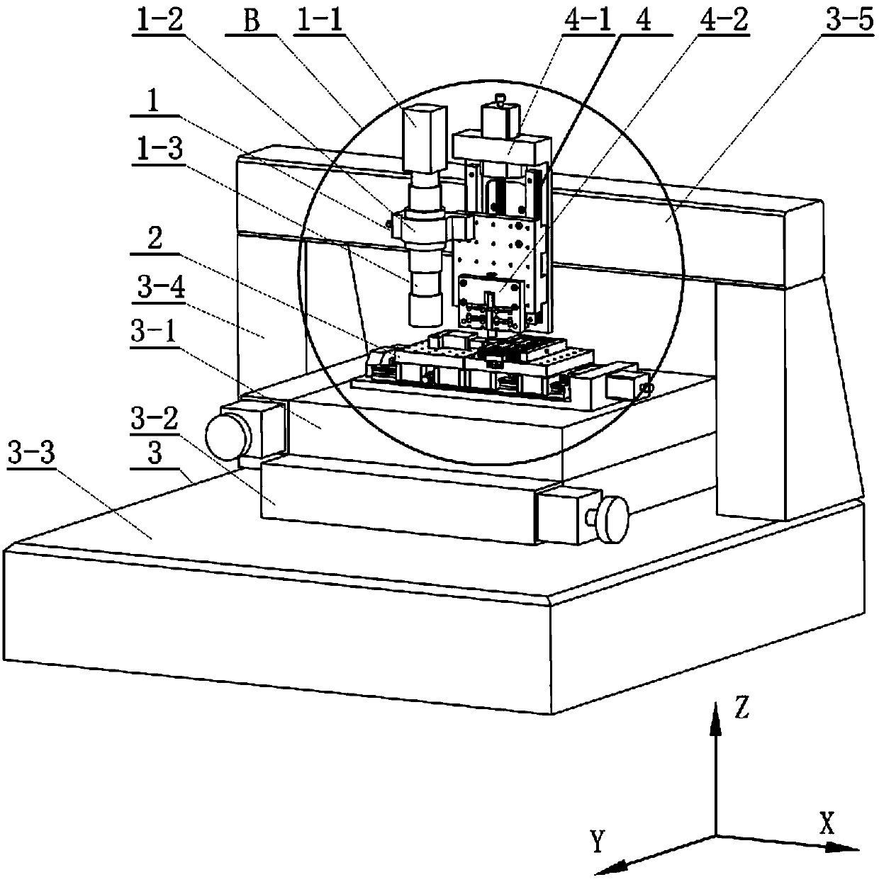
[0019] Specific implementation mode one: as figure 2 , Figure 7 As shown, the micro-component comprehensive mechanical performance testing device includes an in-situ observation system 1, a micro-tensile testing system 2, an auxiliary mechanical system 3 and a dynamic testing system 4; the mechanical auxiliary system 3 includes an X-Y two-dimensional motion platform, Marble vibration isolation platform 3-3, marble beam 3-5 and two marble columns 3-4, the described X-Y two-dimensional motion platform is arranged on the marble vibration isolation platform 3-3, and the Y direction of the X-Y two-dimensional motion platform The motion platform 3-1 is set on the X-direction motion platform 3-2, the micro-tensile testing system 2 is installed on the Y-direction motion platform 3-1, and the dynamic test system 4 is installed on the marble beam 3-5 On the front side, the two ends of the marble beam 3-5 are respectively supported by one of the marble columns 3-4, and the lower ends ...
specific Embodiment approach 2
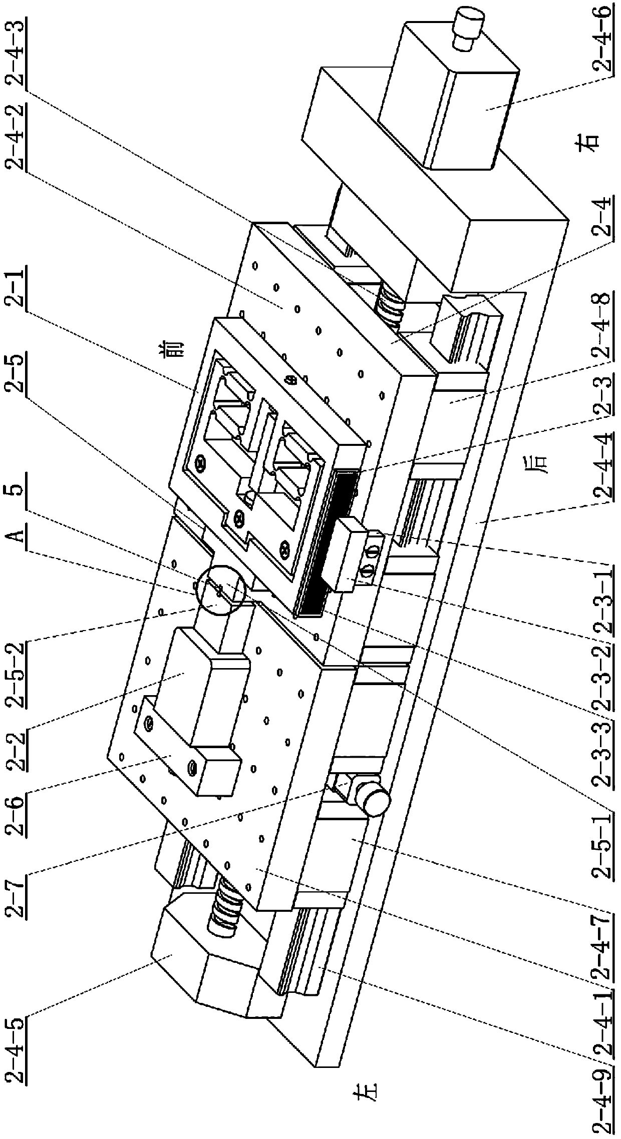
[0020] Specific implementation mode two: as figure 2 , image 3 and Figure 5 As shown in the specific embodiment 1, the micro-component comprehensive mechanical performance testing device, the micro-tensile testing system 2 includes a horizontal precision drive unit 2-1, a micro force sensor 2-2, and a horizontal linear grating measuring device 2-3 , horizontal high-precision electric shift table 2-4, horizontal object stage 2-5, force sensor fixed block 2-6, two fixing parts 2-7, described horizontal high-precision electric shift table 2-4 includes left load Object platform 2-4-1, right loading platform 2-4-2, lead screw nut pair 2-4-3, L-shaped base 2-4-4, support seat 2-4-5, stepping motor 2- 4-6, four left sliders 2-4-7, four right sliders 2-4-8, two guide rails 2-4-9, the horizontal stage 2-5 includes an animal stage 2-5-1 and the static stage 2-5-2, the horizontal linear grating measuring device 2-3 includes the grating ruler reading head installation frame 2-3-1, t...
specific Embodiment approach 3
[0022] Specific implementation mode three: as image 3 , Figure 4 As shown, in the micro-component comprehensive mechanical performance testing device described in Embodiment 2, the horizontal precision drive unit 2-1 includes a first flexible hinge mechanism 2-1-1, a first pre-tightening screw 2-1-2 , the first piezoelectric ceramic 2-1-3, two first gaskets 2-1-4, two steel balls 2-1-5, three first mounting holes 2-1-6, the first The middle part of the flexible hinge mechanism 2-1-1 is provided with a first groove, and the first piezoelectric ceramic 2-1-3 is arranged in the first groove of the first flexible hinge mechanism 2-1-1, and the first The two ends of the piezoelectric ceramic 2-1-3 contact the inner wall of the first groove of the first flexible hinge mechanism 2-1-1 respectively through the steel ball 2-1-5 and the first gasket 2-1-4, and the first The flexible hinge mechanism 2-1-1 is provided with three first installation holes 2-1-6 for fixed connection with...
PUM
 Abstract
Description
Claims
Application Information
 - R&D
- Intellectual Property
- Life Sciences
- Materials
- Tech Scout
- Unparalleled Data Quality
- Higher Quality Content
- 60% Fewer Hallucinations
Browse by: Latest US Patents, China's latest patents, Technical Efficacy Thesaurus, Application Domain, Technology Topic, Popular Technical Reports.
© 2025 PatSnap. All rights reserved.Legal|Privacy policy|Modern Slavery Act Transparency Statement|Sitemap|About US| Contact US: help@patsnap.com


