Magnet flux amount estimation device, abnormal demagnetize determination device, synchronous motor driving device, and electric motor car

A permanent magnet synchronous motor and magnetic flux technology, which is used in the control of electromechanical transmissions, electric vehicles, winding excitation motors, etc., which can solve the problems of time-consuming, inability to detect or estimate the magnetic flux

Active Publication Date: 2014-08-27
KK TOSHIBA
View PDF5 Cites 9 Cited by
  • Summary
  • Abstract
  • Description
  • Claims
  • Application Information

AI Technical Summary

Problems solved by technology

However, this method needs to sequentially apply positive and negative bias currents, it takes time to detect

Method used


Image

  • Magnet flux amount estimation device, abnormal demagnetize determination device, synchronous motor driving device, and electric motor car
  • Magnet flux amount estimation device, abnormal demagnetize determination device, synchronous motor driving device, and electric motor car
  • Magnet flux amount estimation device, abnormal demagnetize determination device, synchronous motor driving device, and electric motor car

Examples


no. 1 approach )

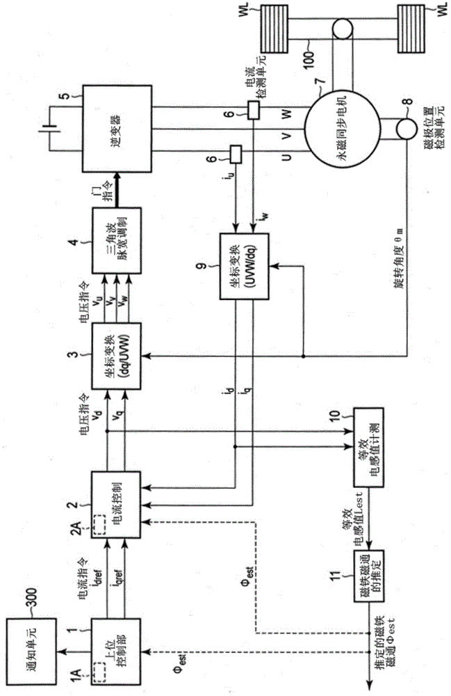
[0037] figure 1 It is a block diagram showing a configuration example of the magnet magnetic flux estimating unit, the synchronous motor drive device, and the electric vehicle according to the first embodiment. In addition, although several embodiment is described below, the same code|symbol is attached|subjected to the structure similar to this embodiment, and description is abbreviate|omitted.

[0038] figure 1 The electric vehicle shown is equipped with a host control unit 1, a current control unit 2, a coordinate conversion unit 3, a triangular wave pulse width modulation unit 4, an inverter 5, a current detection unit 6, a motor 7, a magnetic pole position detection unit 8, and a coordinate conversion unit 9 , an equivalent inductance value measuring unit 10 , a magnet flux estimating unit 11 , a wheel WL, and an axle 100 that transmits rotational power of the AC motor M to the wheel WL.

[0039] The current control unit 2, the coordinate conversion unit 3, and the tria...

no. 2 approach )

[0108] Figure 8 An example configuration of the magnet magnetic flux estimating device, the synchronous motor drive device, and the electric vehicle according to the second embodiment is shown.

[0109] Figure 8 in figure 1 The high-frequency voltage application unit 12, the adder 13 and the high-frequency current amplitude detection unit 14 are newly added on the basis of the above.

[0110] Figure 9 It is an example showing high-frequency voltage and corresponding high-frequency current waveform.

[0111] The high-frequency voltage applying unit 12 outputs, for example, Figure 9 The high-frequency voltage vdhf shown in (a), the high-frequency voltage vdhf is added to the output of the current control unit 2, that is, the d-axis voltage command Vd1 in the adder 13 to calculate a new d-axis voltage command Vd2, and input it to coordinate transformation unit 3.

[0112] The high-frequency current amplitude detection unit 14 measures the amplitude Δihf of the high-freq...

no. 3 approach )

[0122] Figure 10 An example configuration of the magnet magnetic flux estimating device, the synchronous motor drive device, and the electric vehicle according to the third embodiment is shown.

[0123] Figure 10 in figure 1 A d-axis bias current command value generation unit (bias current unit) 15 is added on the basis of the d-axis for passing a bias current to the d-axis. The d-axis bias current command value generation unit 15 generates a d-axis current command value that varies from an initial value at a predetermined rate of increase. Also, the d-axis bias current command value generation unit 15 can be used as figure 1 The high-level control unit 1 is composed of independent elements, and may be an element included in the high-level control unit 1 .

[0124] The magnet magnetic flux estimation unit 11 calculates an estimated value of the magnet magnetic flux based on at least one of the equivalent inductance value Lest and the d-axis bias current command value idr...


PUM


Abstract

The invention refers to a magnet flux amount estimation device, abnormal demagnetize determination device, synchronous motor driving device, and electric motor car. According to one embodiment, a magnet flux amount estimation device includes a magnetic pole position detector configured to detect a magnetic pole position of a permanent magnet synchronous motor including a permanent magnet within a rotor; an inductance-equivalent value determination module configured to determine an inductance-equivalent value of a d-axis corresponding to a determined magnetic pole direction; and a magnet flux amount estimator configured to calculate an estimation value of a magnet flux amount of the permanent magnet, based on the inductance-equivalent value.

Description

[0001] Cross reference to related applications [0002] This application is based on Japanese Patent Application No. 2013-32391 (filing date: February 21, 2013), and the priority of this application is claimed, and the entire content of this application is hereby incorporated by reference. technical field [0003] Embodiments relate to a magnet flux estimation device, an abnormal demagnetization determination device, a synchronous motor drive device, and an electric vehicle. Background technique [0004] In the interior permanent magnet synchronous motor (IPMSM), high torque is obtained by a permanent magnet built into the rotor. The torque generated by the IPMSM is expressed by the torque from the magnet flux, that is, the sum of the magnet torque and the reluctance torque due to the change of the reluctance. Since the magnet torque is a torque proportional to the magnet flux , so once the permanent magnet flux changes, the magnet torque also changes, and the generated tor...

Claims


Application Information

Patent Timeline
IPC IPC(8): H02P6/16H02P6/08B60L3/00B60L9/18H02P6/06H02P6/12H02P6/28H02P21/00H02P21/14H02P21/22H02P27/04H02P27/08
CPCH02P6/00H02P21/0035H02P21/141H02P21/22H02P21/18H02P2207/05H02P21/06H02P6/32
Inventor 安井和也谷口峻鹿野将
Owner KK TOSHIBA
Why Eureka
Try Eureka