Solar semi-shading heat-driven automatic tracking device

An automatic tracking device and solar energy technology, which is applied in the field of solar energy tracking, can solve the problems of large tracking error, slow tracking speed, and large tracking error, etc., and achieve the effect of high tracking accuracy

Inactive Publication Date: 2017-01-18
LANZHOU UNIVERSITY OF TECHNOLOGY
View PDF3 Cites 0 Cited by
  • Summary
  • Abstract
  • Description
  • Claims
  • Application Information

AI Technical Summary

Problems solved by technology

Furthermore, in the early morning or later in the afternoon, the solar radiation becomes weaker, and to ensure a larger temperature difference must require a larger light-receiving area difference, so the gap between the device and the sun's incident light The angle must be further increased, and the tracking error is correspondingly larger
In short, the tracking error of this technology is small at noon, and the tracking error of this technology gradually increases with the increase of the sun's azimuth angle and the weakening of the solar radiation intensity
[0006]3. The device will automatically reset when the cloud is shading the gap, and then track after the sun comes out, but because there is no concentrating device, there is a slow rotation tracking process, which requires a long adjustment time
[0007]4. The rack and pinion transmission is a linear displacement angle conversion device, that is, when the rotation angle of the gear is the same, the displacement distance of the rack is required to remain unchanged, that is, the thermal expansion is required The volume expansion of the fluid remains constant, and in the morning and evening, the amount of solar radiation is small, and the temperature of the thermally expanding fluid rises slowly, so its tracking speed is slower than at noon, and it is difficult to keep the rotation speed of the device constant throughout the day , and it is difficult to keep consistent with the angular velocity of the sun, so its tracking error is relatively large
[0008]5. This technology is easy to shake under strong wind conditions, which may easily cause damage to the device
The double-endothermic cavity differential pressure piston drive device requires filling gaseous substances, or semi-gaseous and semi-liquid substances inside. If the double cavity is completely filled with liquid substances, due to the incompressibility of liquid, the liquid heat-absorbing cavity on the high temperature side will also It is impossible to squeeze the heat-absorbing chamber on the low-temperature side to cause piston displacement. In addition, when the temperature in the double heat-absorbing chambers is high, the volume expansion of the liquid has no place to release, which will cause the heat-absorbing chamber to burst
This kind of device containing gaseous substances inside is easy to shake with the size of the wind under strong wind conditions, resulting in large tracking errors and easy damage to the device

Method used


Image

  • Solar semi-shading heat-driven automatic tracking device
  • Solar semi-shading heat-driven automatic tracking device
  • Solar semi-shading heat-driven automatic tracking device

Examples


Embodiment 1

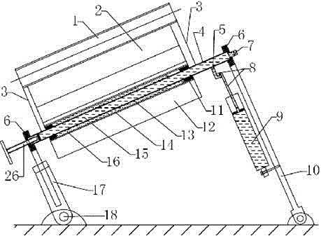
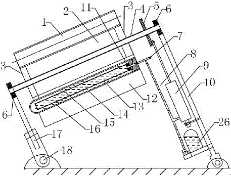
[0031] Such as figure 1 , Figure 4 , Figure 5 As shown, a first heat collecting tube 1 is provided on the focal line position of the first parabolic concentrating groove 2, an opening 19 is provided at the center of the first parabolic concentrating groove 2, and a second parabolic concentrating groove is provided at the opening 19. Groove 12 is provided with second heat collecting tube 14 at the focal line place of second parabolic concentrating groove 12, and the sunlight that shoots to second heat collecting tube 14 from the rear of second parabolic concentrating groove 12 and the side rear direction is first collected The heat pipe 1 and the second parabolic concentrating groove 12 are all blocked, and the sunlight that shoots to the second heat collecting tube 14 from the front and side front of the second parabolic concentrating groove 12 is focused on the second heat collecting tube 14, from the first collecting The sunlight that heat pipe 1 direction radiates to th...

Embodiment 2

[0037] Such as figure 1 , Figure 4 , Figure 5 As shown, on the basis of Embodiment 1, the rotating device 5 is changed into a hollow turntable, the connection mode between the two ends of the rotating shaft 4 and the second bracket 10 is changed into a sliding sleeve connection, and the second bracket 10 is changed into a fixed type at both ends. Yes, the bottom of the second bracket 10 is fixed on the foundation.

[0038] The first parabolic light-gathering groove 2 is placed east-west and rotates north-south. There are 12 first parabolic light-gathering grooves 2, and every 4 are connected in series to form a row, and a total of 3 rows form an array.

Embodiment 3

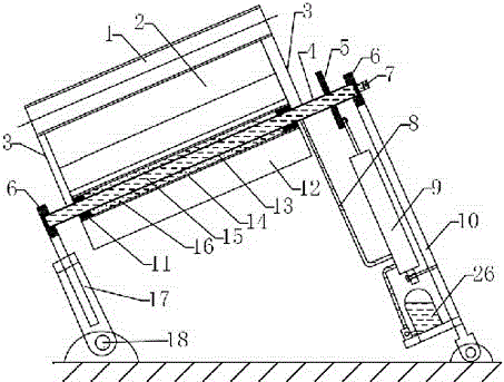
[0040] Such as figure 2 , Figure 4 , Figure 5 As shown, on the basis of Embodiment 1, the rotating device 5 and the pressure guiding tube 8 are changed into a split type, the rotating device 5 is a solid turntable, and a small hole is opened on the rotating shaft 4, and a guide The pressure hose communicates with the hydraulic cylinder.

[0041] The two ends of the rotating shaft 4 are connected to the second support 10 through the bearing 6, the second support 10 is fixed at one end and telescopic at the other end, and the bottom of the second support 10 is fixed on the foundation. A temperature compensation adjustment device (26) is installed on the hydraulic cylinder (9), and the temperature compensation adjustment device (26) is a manual hydraulic pump.

[0042] The first parabolic light-gathering groove 2 is placed east-west and rotates north-south, and there is only one first parabolic light-gathering groove 2 .


PUM


Abstract

A solar semi-shielding type thermal drive automatic tracking device aims at improving tracking accuracy and reducing tracking cost. A heat collection pipe (1) is arranged at the focal line position of a paraboloidal concentration groove (2). An opening (19) is formed in the center of the paraboloidal concentration groove (2). A paraboloidal concentration groove (12) is arranged on the opening (19). A heat collection pipe (14) is arranged at the focal line position of the paraboloidal concentration groove (12). Sunlight which is emitted towards the heat collection pipe (14) from the positions behind and on the rear side of the paraboloidal concentration groove (12) is totally shielded by the first heat collection pipe (1) and the paraboloidal concentration groove (12). Sunlight emitted towards to the heat collection pipe (14) from the positions in front of and on the front side of the paraboloidal concentration groove (12) is focused on the heat collection pipe (14). Sunlight emitted towards the heat collection pipe (14) from the heat collection pipe (1) is partly shielded. An expansion pipe (13) is arranged inside the heat collection pipe (14). An inner cavity of the expansion pipe (13) is communicated with an inner cavity of a hydraulic cylinder (9) through a pressure guide pipe (8).

Description

technical field [0001] The invention belongs to the technical field of solar tracking, and in particular relates to a technology and a device for tracking the position of the sun by using sunlight to heat an expansion fluid in a heat collecting tube. Background technique [0002] The direct sun incident light at a certain point on the earth is changing at any time. In order to utilize the direct sun radiation energy as much as possible, the solar energy utilization device is required to be equipped with a device that can track the position of the sun. Most solar tracking devices are mainly electric drive devices. This type of device has high tracking accuracy, but energy consumption and high cost in the tracking process. A device that can track the position of the sun through the energy of sunlight, that is, a device that tracks the sun through the sun, has no energy consumption, low cost, and easy maintenance, and has high application prospects and market value. [0003] S...

Claims


Application Information

Patent Timeline
Patent Type & Authority Patents(China)
IPC IPC(8): H02S20/32F24J2/38G05D3/12F24S50/20
CPCY02E10/47Y02E10/50
Inventor 王克振巩景虎魏来韦春晖吴干永程新生李浩彭笙洋
Owner LANZHOU UNIVERSITY OF TECHNOLOGY
Why Eureka
Try Eureka