Solar concentrating thermal drive automatic tracking device

An automatic tracking device and solar concentrating technology, which is applied in the field of solar tracking, can solve the problems of large tracking error, difficulty in keeping the rotation speed of the device constant, and high light intensity, and achieve the effect of high precision and synchronous tracking with small intermittent tracking

Inactive Publication Date: 2015-12-30
LANZHOU UNIVERSITY OF TECHNOLOGY
View PDF9 Cites 0 Cited by
  • Summary
  • Abstract
  • Description
  • Claims
  • Application Information

AI Technical Summary

Problems solved by technology

Furthermore, in the early morning or later in the afternoon, the solar radiation becomes weaker, and to ensure a larger temperature difference must require a larger light-receiving area difference, so the gap between the device and the sun's incident light The angle must be further increased, and the tracking error is correspondingly larger
In short, the tracking error of this technology is small at noon, and the tracking error of this technology gradually increases with the increase of the sun's azimuth angle and the weakening of the solar radiation intensity
[0006]3. This technology requires high light intensity to start, the ambient temperature has a great influence on the device, and the annual operating time is relatively short
This technology is a non-concentrating tracking technology. Due to the small solar flux density, it needs to produce obvious temperature differences and strong solar radiation, so the starting light intensity is high; When the ambient temperature is very low, the heat energy generated by the limited solar radiation will also be lost to the surrounding environment, and no obvious temperature difference can be generated. Therefore, this technology requires high starting light intensity, and the ambient temperature has a great influence on the device. shorter run time
[0007]4. The rack and pinion transmission is a linear displacement angle conversion device, that is, when the rotation angle of the gear is the same, the displacement distance of the rack is required to remain unchanged, that is, the required The volume expansion of the heat-expanding fluid remains constant, and in the morning and evening, the amount of solar radiation is small, and the temperature of the heat-expanding fluid rises slowly, so its tracking speed is slower than that at noon, and it is difficult to keep the rotation speed of the device constant throughout the day. change, and it is difficult to keep consistent with the angular velocity of the sun, so its tracking error is relatively large
[0008]5. This technology is easy to shake under strong wind conditions, which may easily cause damage to the device
The double-endothermic cavity differential pressure piston drive device requires filling gaseous substances, or semi-gaseous and semi-liquid substances inside. If the double cavity is completely filled with liquid substances, due to the incompressibility of liquid, the liquid heat-absorbing cavity on the high temperature side will also It is impossible to squeeze the heat-absorbing chamber on the low-temperature side to cause piston displacement. In addition, when the temperature in the double heat-absorbing chambers is high, the volume expansion of the liquid has no place to release, which will cause the heat-absorbing chamber to burst
This kind of device containing gaseous substances inside is easy to shake with the size of the wind under strong wind conditions, resulting in large tracking errors and easy damage to the device

Method used


Image

  • Solar concentrating thermal drive automatic tracking device
  • Solar concentrating thermal drive automatic tracking device
  • Solar concentrating thermal drive automatic tracking device

Examples


Embodiment 1

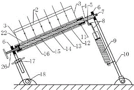
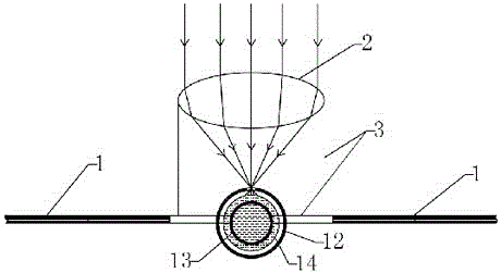
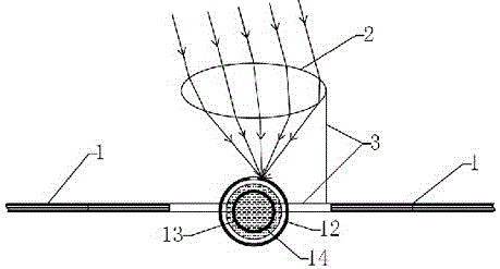
[0031] Such as figure 1 , figure 2 , image 3 , Figure 5 , Figure 8 As shown, the solar receiver 1 is two sets of solar photovoltaic cell components installed in parallel, and a solar concentrator 2 is arranged in the middle of the solar receiver 1, and the type of the solar concentrator 2 is a Fresnel-type line-focusing light-transmitting Mirror, on the focal line position of solar concentrator 2, be provided with heat collecting tube 14, be provided with thermal expansion tube 13 inside heat collecting tube 14, heat collecting tube 14 and thermal expansion tube 13 are split type, on the inner wall of heat collecting tube 14 and thermal expansion The outer walls of the tubes 13 are filled with a heat-conducting medium 16, cork or rubber plugs 11 are provided at the ports at both ends of the heat collecting tube 14, and a reflective layer 12 is wrapped around the heat collecting tube 14, and the reflective layer 12 faces the solar collector A thin groove 22 is opened at...

Embodiment 2

[0036] Such as figure 1 , Figure 4 , Figure 5 , Figure 9 As shown, on the basis of Embodiment 1, the solar receiver 1 is changed into a solar trough concentrator, the type of the solar concentrator 2 is changed into a line focusing trough reflector, and the heat collecting tube 14 and the thermal expansion tube 13 are integrated Type, the inner wall of the heat collecting tube 14 is integrated with the outer wall of the thermal expansion tube 13. At this time, there is no heat conducting medium 16, no cork or rubber stopper 11, and an insulating layer is provided between the heat collecting tube 14 and the reflective layer 12. A reflective layer 12 is wrapped outside the thermal insulation layer, and a thin groove 22 is provided at the position where the reflective layer 12 faces the solar concentrator 2 .

[0037] The temperature compensation adjustment device 26 installed on the expansion tube 13 is a screw rod stretched into the thermal expansion fluid medium 15, the ...

Embodiment 3

[0041] Such as figure 1 , Figure 8 As shown, on the basis of embodiment 1, the solar receiver 1 is changed into a solar dish concentrator, a solar concentrator 2 is arranged in the middle of the solar receiver 1, and the type of the solar concentrator 2 is changed into a point Focusing disc reflector, the thermal expansion tube 13 and the rotating shaft 4 are split, the heat collection tube 14 and the thermal expansion tube 13 are integrated, the heat collection tube 14 and the thermal expansion tube 13 are spherical, and there is a reflector outside the heat collection tube 14 Layer 12, an insulating layer is provided between the heat collecting tube 14 and the reflective layer 12, and an aperture 22 is provided at the position where the reflective layer 12 faces the solar concentrator 2.

[0042] A pressure relief valve 7 and a temperature compensation adjustment device 26 are installed on the pressure guide pipe 8, the temperature compensation adjustment device 26 is a ma...


PUM


Abstract

Solar concentrating heat-driven automatic tracking device, the purpose of which is to use the energy provided by solar heat to drive the device to track changes in the sun's position, improve tracking accuracy, and reduce tracking costs. A solar concentrating device is installed in the middle or around the solar receiver (1). The optical device (2) is provided with a heat collecting tube (14) at the focus or focal line position of the solar concentrator (2), and a thermal expansion tube (13) is arranged inside the heat collecting tube (14), and a thermal expansion tube (13) is arranged inside the heat collecting tube (14). A light-reflecting layer (12) is wrapped on the outside, and small holes or fine grooves (22) are opened on the position where the light-reflecting layer (12) faces the solar concentrator (2), and the thermal expansion tube (13) passes through the pressure guiding tube (8 ) communicates with the inner cavity of the hydraulic cylinder (9), and the inner cavity of the thermal expansion tube (13), the pressure guide tube (8) and the hydraulic cylinder (9) is filled with thermal expansion fluid medium (15), and the hydraulic cylinder (9) One end is connected with the second bracket (10), and the other end is connected with the displacement angle conversion device (5).

Description

technical field [0001] The invention belongs to the technical field of solar tracking, and in particular relates to a technology and a device for tracking the position of the sun by utilizing the sun's concentrated heat to expand the fluid to drive the transmission to rotate after being heated and expanded. Background technique [0002] The incident light of the sun at a certain point on the earth is changing at any time. In order to use the direct solar radiation energy as much as possible, the solar energy utilization device is required to be equipped with a device that can track the position of the sun. Most solar tracking devices are mainly electric drive devices. This type of device has high tracking accuracy, but energy consumption and high cost in the tracking process. A device that can track the position of the sun through the energy of sunlight, that is, a device that tracks the sun through the sun, has no energy consumption, low cost, and easy maintenance, and has ...

Claims


Application Information

Patent Timeline
Patent Type & Authority Patents(China)
IPC IPC(8): F24J2/06F24J2/46F24S23/00
CPCY02E10/44
Inventor 王克振岳金文隋增光邓立张舒研杨春林
Owner LANZHOU UNIVERSITY OF TECHNOLOGY
Why Eureka
Try Eureka