Method for monitoring catalyst circulation volume of catalytic cracking apparatus

A catalytic cracking unit and catalyst recycling technology, applied in catalytic cracking, cracking, hydrocarbon oil cracking, etc., can solve the problem that the catalyst circulation volume cannot meet the real-time requirements, the real-time performance cannot meet the advanced control of the riser, and the accuracy is difficult to be guaranteed, etc. problem, to achieve the effect of product distribution, promotion and easy transformation

Active Publication Date: 2014-06-04
PETROCHINA CO LTD
View PDF7 Cites 0 Cited by
  • Summary
  • Abstract
  • Description
  • Claims
  • Application Information

AI Technical Summary

Problems solved by technology

[0007] 2. Calculation of the catalyst circulation by using the heat balance of the regenerator has high accuracy, but the temperature and coke content have a certain time lag for the regenerator; the raw catalyst flows from the riser to the regenerator through the stripping section, and its temperature and coke The content has a time lag of 1-2 minutes for the regenerator, and the real-time performance of its calculation cannot meet the requirements for advanced control of the riser
[0008] 3. Use the material balance of carbon in the regenerator and stripper to calculate the catalyst circulation amount. The carbon content of the raw catalyst and the carbon content of the regenerated catalyst can only be obtained through off-line testing, which has a considerable time lag. Therefore, using carbon balance Calculation of catalyst circulation volume by method can not meet the real-time requirements of production monitoring and control
When the opening of the regeneration valve changes greatly or the fluidization state of the catalyst changes, if a fixed regeneration valve characteristic model is used for calculation, its accuracy will not be guaranteed

Method used


Image

  • Method for monitoring catalyst circulation volume of catalytic cracking apparatus
  • Method for monitoring catalyst circulation volume of catalytic cracking apparatus
  • Method for monitoring catalyst circulation volume of catalytic cracking apparatus

Examples


Embodiment 1

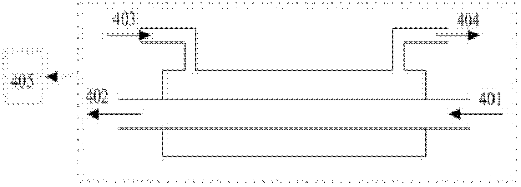
[0025] use figure 2 In the given processing unit, the pipe diameter ratio of the conveying medium pipe and the waiting catalyst conveying pipe is 4. According to the normal riser catalytic cracking reaction, the temperature of the inlet catalyst 401 is 438°C, and the temperature of the outlet catalyst 402 is 365°C. When the medium is air, the flow rate of the medium inlet 403 is 550 L / h, the temperature is 29°C, the temperature of the medium outlet 404 is 375°C, and the value of the control module 405 is 4.2kg / h.

Embodiment 2

[0027] use figure 2 In the given processing unit, the pipe diameter ratio of the conveying medium pipeline and the spent catalyst conveying pipeline is 10. According to the normal riser catalytic cracking reaction, the temperature of the inlet catalyst 401 is 432°C, and the temperature of the outlet catalyst 402 is 350°C. When the medium is nitrogen, the flow rate of the medium inlet 403 is 1300L / h, the temperature is 32°C, the temperature of the medium outlet 404 is 368°C, and the value of the control module 405 is 9.6kg / h.

Embodiment 3

[0029] use figure 2 In the given processing unit, the pipe diameter ratio of the conveying medium pipeline and the spent catalyst conveying pipeline is 20. According to the normal riser catalytic cracking reaction, the temperature of the inlet catalyst 401 is 425°C, and the temperature of the outlet catalyst 402 is 310°C. When the medium is water vapor, the flow rate of the medium inlet 403 is 3100L / h, the temperature is 110°C, the temperature of the medium outlet 404 is 355°C, and the value of the control module 405 is 12.2kg / h.


PUM


Abstract

A method for monitoring a catalyst circulation rate in a catalytic cracking apparatus. A processing unit (4) is arranged on a spent catalyst convey line (5) between a stripper (2) and a regenerator (3) of the catalytic cracking apparatus. The processing unit (4) comprises a temperature control system, a flow rate control system, and a control module system (405). In the processing unit (4), a spent catalyst flows to an outlet (402) near the regenerator end from an inlet (401) near the bottom of the stripper, the temperature changes from T1 to T2, and the temperature is measured and recorded by the temperature control system; a conveying medium and the spent catalyst flow in opposite directions, a flow rate of the conveying medium is F1, the flow rate is measured and recorded by the flow rate control system, the conveying medium flows from an inlet (403) near the regenerator end to an outlet (404) near the bottom of the stripper, the temperature changes from T3 at the inlet to T4 at the outlet, and the temperature is measured and recorded by the temperature control system; the control module (405) displays a catalyst circulation rate in real time, and the formula adopted by the module (405) in calculating the catalyst circulation rate is: catalyst circulation rate=2xF1x[(T4-T3) / (T1-T2)]-1000.

Description

technical field [0001] The invention relates to a method for monitoring catalyst circulation, in particular to a method for on-line monitoring catalyst circulation of a catalytic cracking unit. Background technique [0002] Catalytic cracking unit is one of the most important heavy oil conversion units in petroleum refineries. Under the action of the hot catalyst, the raw oil cracks the heavy oil and transforms it into high-value products such as rich gas, gasoline and diesel. In terms of economic benefits, more than half of the benefits of oil refineries are obtained by catalytic cracking. Therefore, the application of advanced optimization control technology to realize the stable operation of the device and provide conditions for online optimization undoubtedly has important practical significance and obvious economic benefits. [0003] Most of the existing catalytic cracking optimization control schemes are mainly based on the reaction temperature (riser outlet temperat...

Claims


Application Information

Patent Timeline
Patent Type & Authority Patents(China)
IPC IPC(8): C10G11/00C10G47/36
CPCC10G47/36C10G11/00C10G11/187C10G11/182
Inventor 张忠东柳召永高雄厚高永福王智峰马燕青侯凯军刘明霞田爱珍张志国
Owner PETROCHINA CO LTD
Why Eureka
Try Eureka